Documents and articles detailing how to do specific tasks in IP4G
This is the multi-page printable view of this section. Click here to print.
How-to
How to Guides for Common IP4G Tasks
- 1: General How-To Documents
- 1.1: Creating a virtual machine
- 1.2: CPU Types
- 1.3: Creating a new VM with an SSH key for root
- 1.4: Importing an OVA file into your Power cloud instance
- 1.5: Capturing and exporting a virtual machine
- 2: Oracle on IP4G
- 3: AIX How-To Documents
- 3.1: Preparing systems for migration
- 3.2: Migrating to IP4G using a mksysb and alt_disk_mksysb
- 3.3: AIX MPIO Recommendations
- 3.4: AIX TCP/IP Settings
- 3.5: Install gcloud SDK on AIX
- 3.6: RMC details and troubleshooting
- 3.7: RMC and AIX 6.1
- 4: IBM i How-To Documents
- 4.1: Accessing the IBM i Console
- 4.2: Accessing IBM i Virtual Machines
- 4.3: Preparing systems for migration
- 4.4: Configuring an IBM i Virtual Machine Instance
- 5: Linux How-To Documents
- 6: Storage Based Replication
- 6.1: Introduction
- 6.2: Configuration
- 6.3: Failover and Failback
- 6.4: Management
- 6.5: Monitoring
- 6.6: FAQ
- 6.7: Best Practices
- 6.8: Examples
- 6.9: Troubleshooting
1 - General How-To Documents
General how-to guides for IP4G
General guides and how-to documents for IP4G that apply to any operating system.
1.1 - Creating a virtual machine
Complete the following steps to create and configure an IBM Power for Google Cloud (IP4G) virtual machine (VM).
Creating an IP4G virtual machine instance
Follow these steps to create an IP4G virtual machine instance from the GUI. To create one from the CLI, see CLI VM Creation
- Navigate to the IP4G User Interface.
- Click Create VM from the left navigation bar (nav bar).
- Click Create Instance at the top of the list of VMs.
If no customer-specific images have been created, import a stock image. See Adding Images to the Image Catalog
Configuring a Power Systems virtual machine instance
Follow these steps to configure a new virtual machine instance.
Complete all the fields under the virtual machines section.
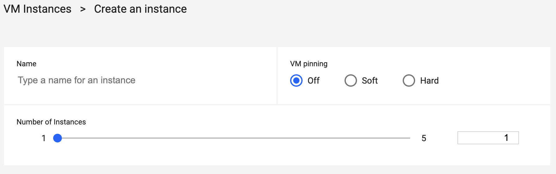
- Name - Input a name for the virtual machine.
- VM pinning - Select one of the options. Note that VM pinning is not available in all regions.
- Number of Instances - Use the slide bar to set the number of instances. When creating an IBM i VM, this can only be set to 1.
When more than one instance is selected, Affinity Policy and Naming Convention information is available.
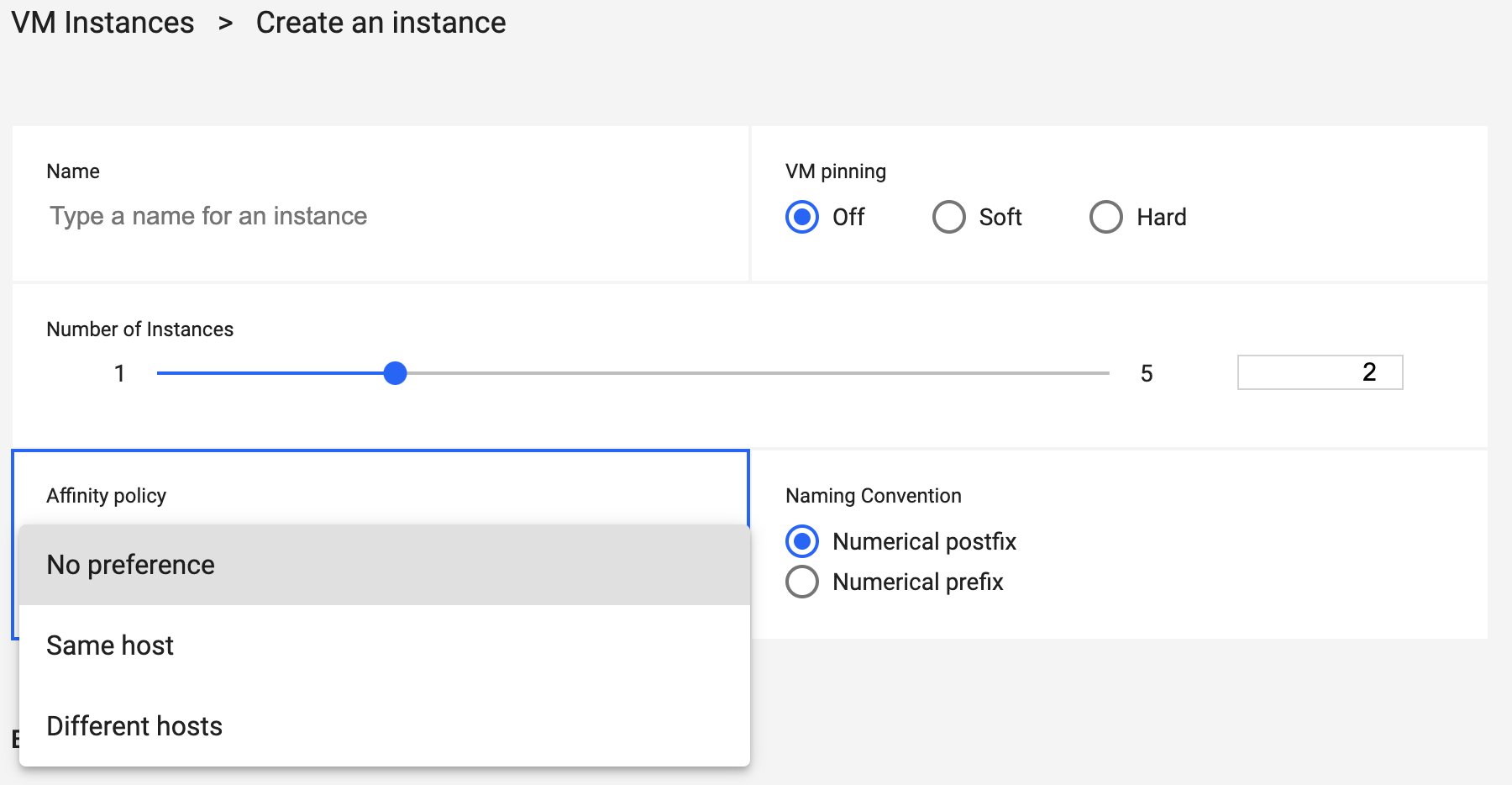
- Affinity Policy - Select the proper option. Not available for IBM i.
- Virtual Machine Naming Convention - Select Postfix or Prefix to add a suffix or prefix to VMs.
Complete the Boot Image fields. Select the proper type from the drop-down menus.
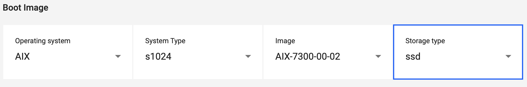
- Operating system - Select the VM’s operating system.
- System Type - Select the VM’s operating system.
- Image - Select the VM’s image.
- Storage type - Select the storage type.
Complete the Processing Profile fields.
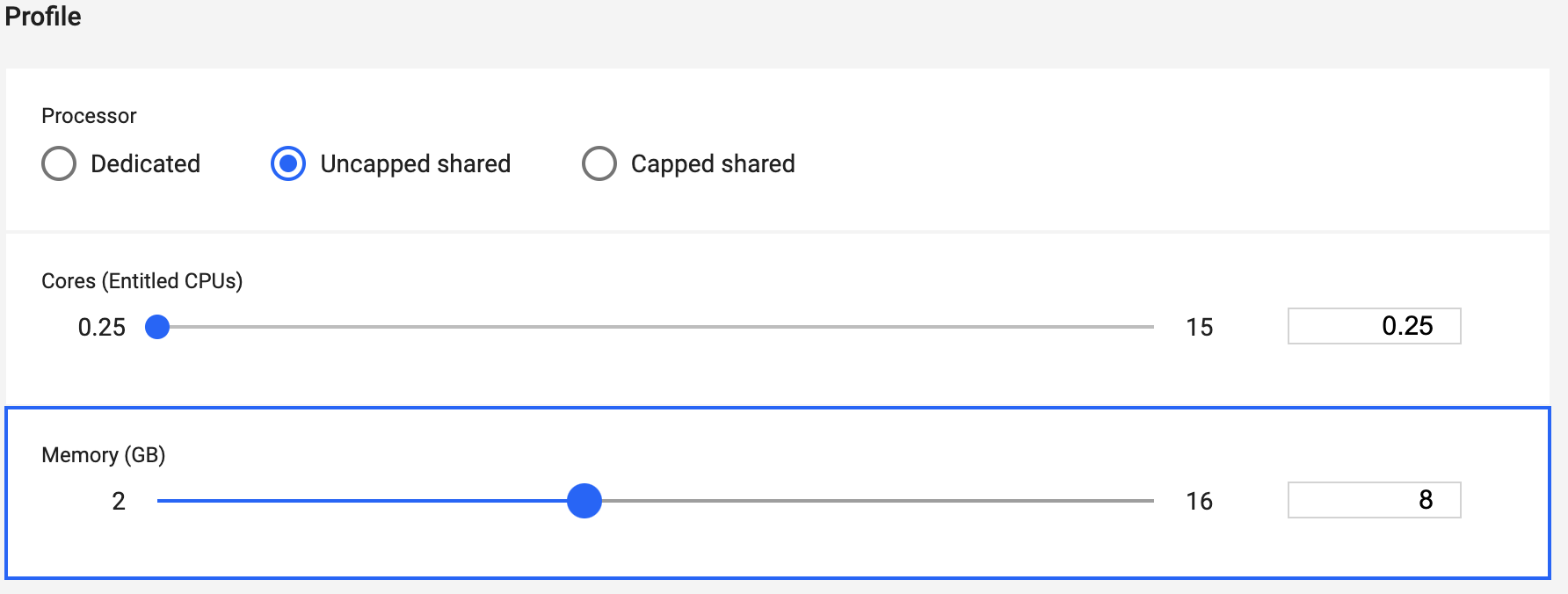
- Processor - Select the correct processor type.
- Cores - Use the slider to select the desired number of cores.
- Memory - Use the slider to set the amount of memory, in GBs.
Complete the Networks fields.
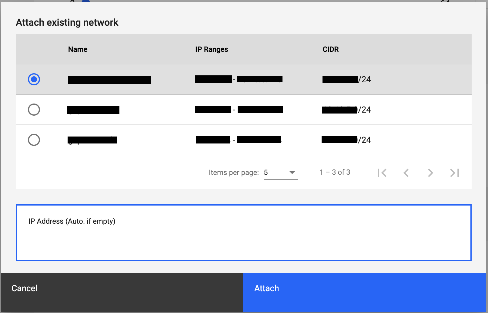
- Attach existing network - Select the network to attach from the listed options.
- IP Address - Optional. Provide the VM’s TCP/IP address. If not set specifically, one will be assigned automatically.
Complete the Volumes fields.
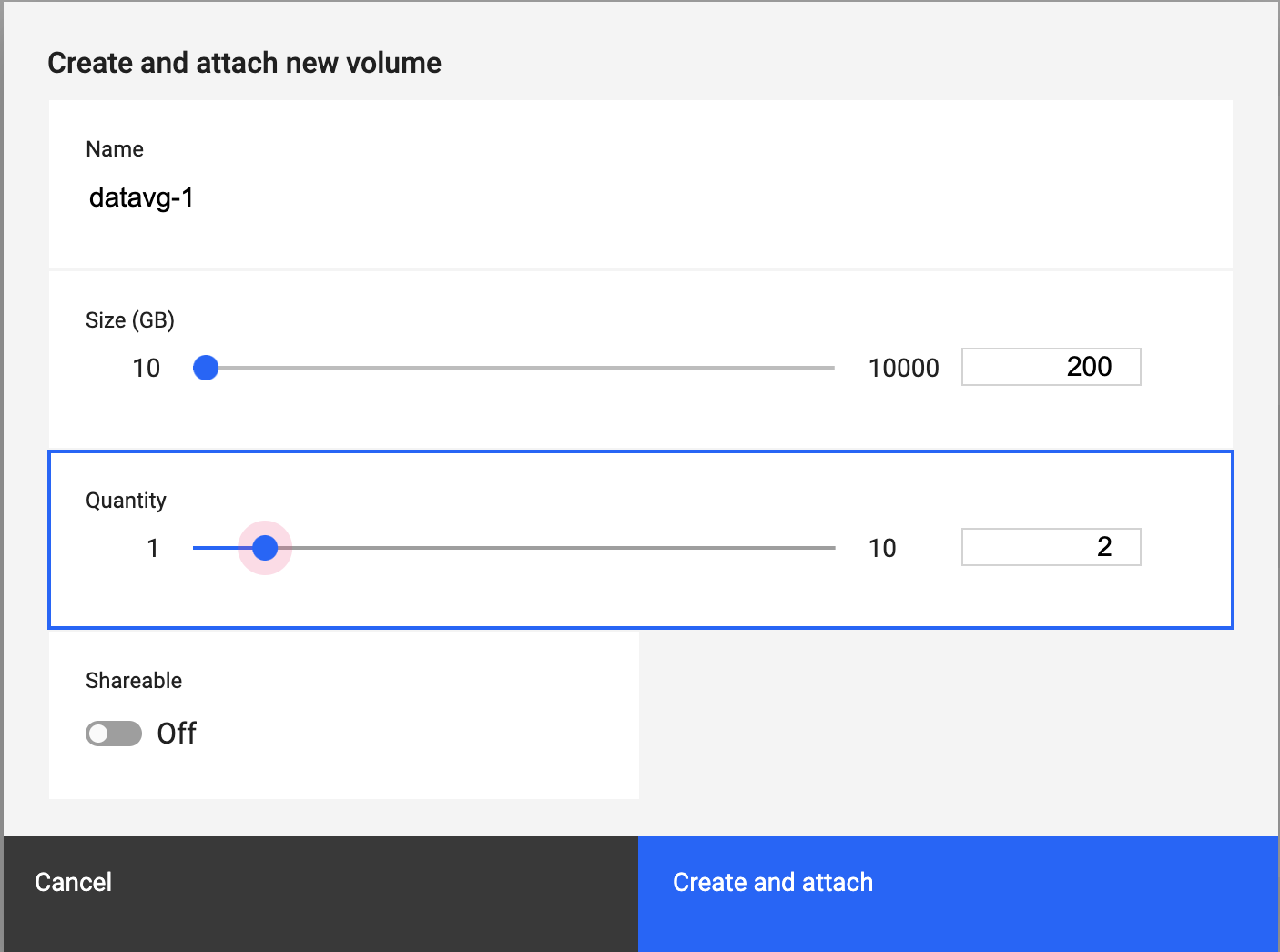
- Name - Use this field to put in a name for the volume.
- Size - Use the slider to set the volume size, in GBs.
- Quantity - Use the slider to set the number of volumes.
- Shareable - Use this to toggle the ability for sharing volumes.
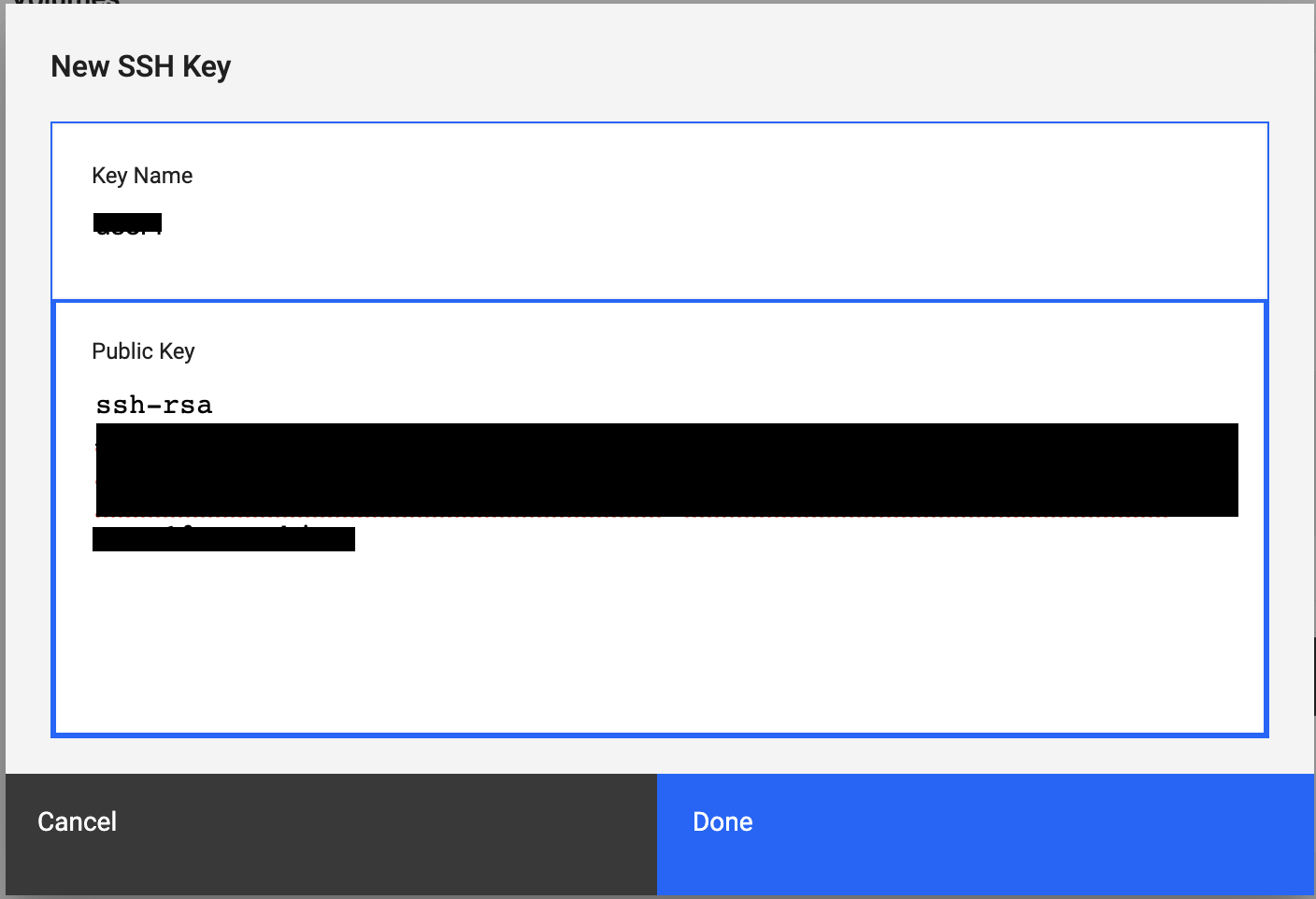
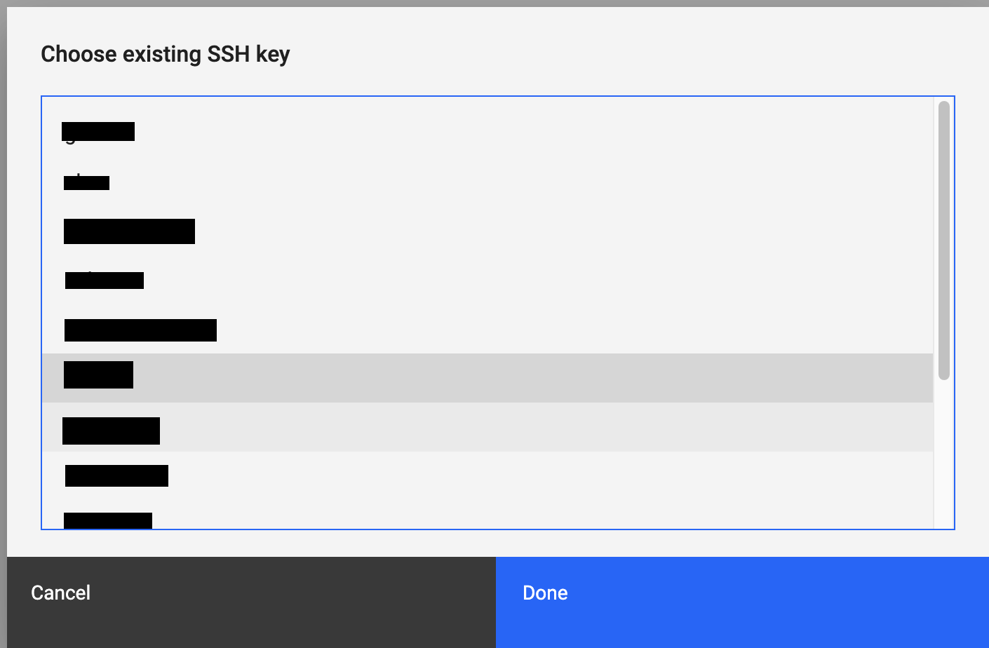
Complete the various SSH Key fields. Choose to create a new SSH or use an existing.

- New SSH Key
- Choose existing SSH key
Review your selections for accuracy and submit the form.
1.2 - CPU Types
CPU Types in IBM Power for Google Cloud Platform (IP4G)
A Virtual Machine’s (VM) CPU allocation is determined by its Entitlement. Entitlement represents the guaranteed minimum amount of physical CPU resources available to the VM. When you provision a VM and set its Entitlement, you ensure that the VM will receive at least that level of CPU performance when needed. The vCPU value, which indicates the number of virtual processors available to the VM, is derived from the Entitlement. For VMs using shared processors, the vCPU value is set to the Entitlement rounded to the nearest whole number. In the case of VMs with dedicated processors, the vCPU value is equal to the Entitlement.
There are two primary processor types. Shared and dedicated. Shared processors can be broken down into capped or uncapped shared processors.
| CPU Type | Increment | Description |
|---|---|---|
| uncapped shared | 0.25 | CPU entitlement is guaranteed, vCPU is set to Entitlement rounded up to the nearest whole number. CPU may consume up to the vCPU value if busy. |
| capped shared | 0.25 | CPU entitlement is guaranteed, vCPU is set to Entitlement, rounded up to the nearest whole number. VM Cannot consume more CPU than its entitlement. |
| dedicated | 1 | CPU entitlement is guaranteed, VM is allocated whole CPUs. |
1.3 - Creating a new VM with an SSH key for root
You can set up one or more SSH keys for root login when you create new virtual machines (VM) on a Power cloud instance. The keys are loaded into the root’s authorized_keys file. SSH keys allow you to securely log in to a VM. You must use the available operating system options to create SSH keys. To generate SSH keys on a Linux® or Mac OS system, for example, you can use the standard ssh-keygen tool.
Setting up an SSH key to be used in a VM create
In this example, the user created a public key on a Linux-based GCP compute instance by using the ssh-keygen tool:
> $ cat .ssh/id_rsa.pub
ssh-rsa AAAAB3NzaC1yc2EAAAADAQABAAABAQCtuQnQOc2k4zaGzE7b3xUMCjUy++s/9O9HE4fXSm7UNKoTY39zjQ8mhOwaA3HEo12tOdzdFDYHHWNOYufCcFFk61CAL6HyQGGClib1nFc1xUcgTI9Dee8zzaAsN8mIIr1CgbRELhvOsTv23U4QddpfjkcVoKfF0BAtxgauvooQdPZBoxa2rsD+BvcWnjglkYWG2aBbuzFvSl1fLMihjfej8w1lxbcsYEcJg2X96NJPLmLsEJ+XwoXfVuv0X4z8IoBzZ8UbyTlrDv73EAH34GViYfZFbrIaNnwnz/f/tuOKcINihH72YP+oZn9JeiHQ+hKpMqJAmOK2UIzYr3u+79n9 testkey
To use an SSH key with a VM create operation, you must first add the public key to the cloud instance by using the pcloud compute sshkeys create command. To add the ssh-keygen-generated public key, enter the following command (replacing the public key value with your own):
Important: You must enclose the --publickey value in quotations.
$ pcloud compute sshkeys create testkey --publickey "ssh-rsa AAAAB3NzaC
1yc2EAAAADAQABAAABAQCtuQnQOc2k4zaGzE7b3xUMCjUy++s/9O9HE4fXSm7UNKoTY39zjQ8mhOwaA3HEo12tOdzdFDYHHWNOYufCcFFk61CAL6HyQGGClib1nFc1xUcgTI9Dee8zzaAsN8mIIr1CgbRELhvOsTv23U4QddpfjkcVoKfF0BAtxgauvooQdPZBoxa2rsD+BvcWnjglkYWG2aBbuzFvSl1fLMihjfej8w1lxbcsYEcJg2X96NJPLmLsEJ+XwoXfVuv0X4z8IoBzZ8UbyTlrDv73EAH34GViYfZFbrIaNnwnz/f/tuOKcINihH72YP+oZn9JeiHQ+hKpMqJAmOK2UIzYr3u+79n9 testkey"
SSHKey created: testkey
To confirm that the key was successfully added, use the pcloud compute sshkeys list command.
$ pcloud compute sshkeys list
Name      Key                                          CreationDate
testkey   ssh-rsa AAAAB3NzaC1y...UIzYr3u+79n9 testkey  2019-07-26T18:21:56.030Z
Creating a VM instance with a configured SSH key
Now that you’ve added the key to the cloud instance, you can create a new VM with the key by using the following command:
$ pcloud compute instances create keytest-vm -i AIX-7200-03-03 -t shared -p 0.5 -m 5 -n gcpnetwork -k testkey
The preceding VM create operation resulted in a new AIX VM with an IP address of 172.16.7.16. You can now SSH to the AIX VM can from a connected system, which is configured with the private key for testkey. In the following example, the connecting system is a GCP x86 compute instance with direct connectivity to the Power cloud instance network.
$ ssh root@172.16.7.16
Enter passphrase for key '/home/keytest/.ssh/id_rsa':
Last login: Fri Jul 26 16:53:22 CDT 2019 on ssh from 10.150.0.11
*******************************************************************************
*                                                                             *
*                                                                             *
*  Welcome to AIX Version 7.2!                                                *
*                                                                             *
*                                                                             *
*  Please see the README file in /usr/lpp/bos for information pertinent to    *
*  this release of the AIX Operating System.                                  *
*                                                                             *
*                                                                             *
*******************************************************************************
# oslevel -s
7200-03-03-1914
#
On this AIX VM, you can find the testkey value in the authorized_keys file.
> \# cat .ssh/authorized_keys
ssh-rsa AAAAB3NzaC1yc2EAAAADAQABAAABAQCtuQnQOc2k4zaGzE7b3xUMCjUy++s/9O9HE4fXSm7UNKoTY39zjQ8mhOwaA3HEo12tOdzdFDYHHWNOYufCcFFk61CAL6HyQGGClib1nFc1xUcgTI9Dee8zzaAsN8mIIr1CgbRELhvOsTv23U4QddpfjkcVoKfF0BAtxgauvooQdPZBoxa2rsD+BvcWnjglkYWG2aBbuzFvSl1fLMihjfej8w1lxbcsYEcJg2X96NJPLmLsEJ+XwoXfVuv0X4z8IoBzZ8UbyTlrDv73EAH34GViYfZFbrIaNnwnz/f/tuOKcINihH72YP+oZn9JeiHQ+hKpMqJAmOK2UIzYr3u+79n9 testkey
1.4 - Importing an OVA file into your Power cloud instance
You can import an OVA file to bring a new VM image and any attached data volumes into your Power cloud instance. An OVA file is an industry standard format that is used to package VM boot disk images and any related data volume images. If you are running an IBM Cloud PowerVC Manager 1.4.1, or later, landscape in your local environment, you can generate OVA files from your Power LPARs.
To bring an OVA file into your cloud instance image catalog and deploy it as a new VM, complete the following steps:
Start with a local OVA file that was generated by your existing PowerVC instance.
Upload the OVA file into a selected Google Cloud Storage bucket.
Set up access keys to the Google Cloud Storage bucket.
Note: Issuing the operation that imports the OVA file into your cloud instance provides the access keys.
Import the OVA file by using either the web UI or running the
pcloudcommand.After the import operation is complete, you can deploy a VM by using the new image in your image catalog.
Setting up a cloud storage bucket
You can set up a cloud storage bucket by using the pcloud command to import OVA files.
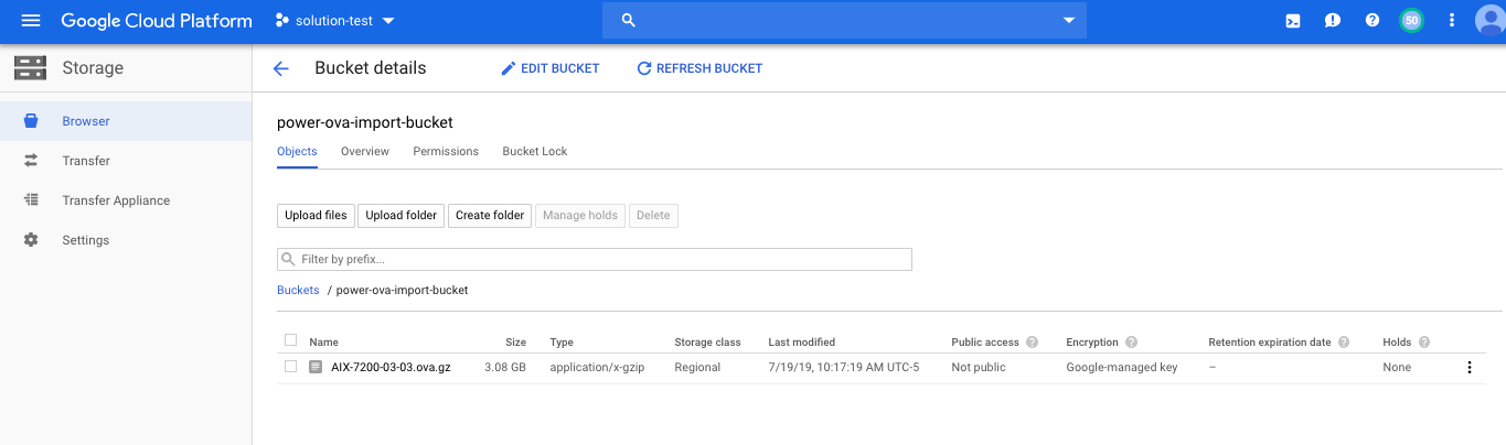
To begin, you must create a cloud storage bucket. The following graphic provides an overview of a user-created cloud storage bucket named power-ova-import-bucket. The Link for gsutil field contains access information that is an important part of the import operation.

To enable access to the cloud storage bucket for the Power Systems IaaS management service, you must create a storage access key. You can create a storage access key in the settings area of the cloud bucket management UI.
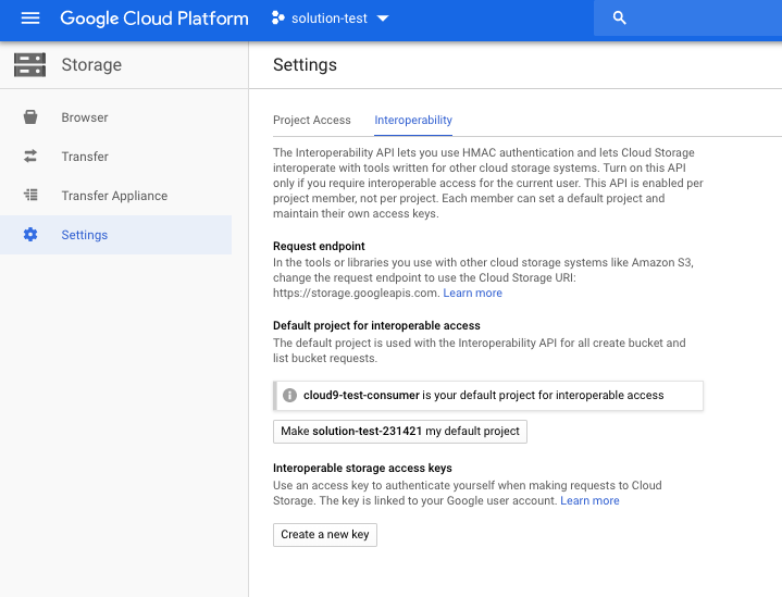
Selecting the create a new key option generates the access key and secret as shown in the following example:
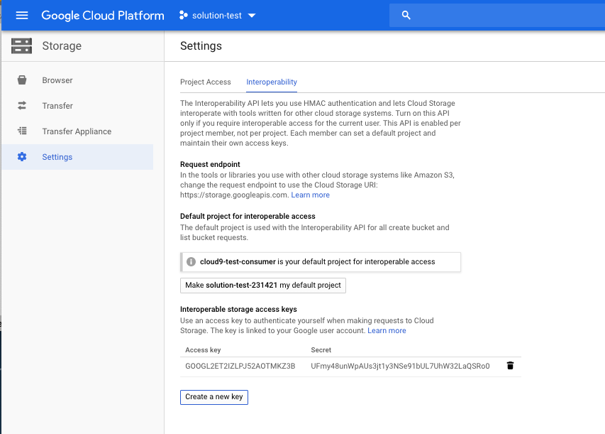
After you generate an access key and secret, the cloud storage bucket can hold OVA files and be used with the Power IaaS management service image import feature. You can upload files to the cloud storage bucket by using the upload files feature of the web UI or with the gsutil command. For more information, visit the Google Cloud Storage Documentation site.
In the following example, a user created an OVA file that is named AIX-7200-03-03.ova.gz and placed it in the cloud storage bucket.
Importing the OVA file into your cloud instance by using the pcloud command
The pcloud compute images import command imports an OVA file. For pcloud compute images import command usage and flag details, refer to the following code block:
$ pcloud compute images import -h

Import a new Image for a Cloud Instance.

Usage:
  pcloud compute images import <ImageName> --bucketname <Bucket> --filename <ImageFileName> --accesskey <AccessKey> --secretkey <SecretKey> [flags]

Flags:
  -a, --accesskey string     Cloud Storage Access Key (required)
  -b, --bucketname string    Cloud Storage Bucket (bucket name plus optional folders): bucket-name[/folder/../] (required)
  -f, --filename string      Cloud Storage Image File Name, should end with .ova, .ova.gz, .tar, .tar.gz or .tgz (required)
  -h, --help                 help for import
  -s, --secretkey string     Cloud Storage Secret Key (required)
  -t, --storagetype string   Storage Type (must be one of {"standard", "ssd"}) (default "standard")

Global Flags:
  -F, --format string      Available formats: 'table', 'yaml', 'json', 'csv'.
                            Default is command specific.
                            Can be used with describe and list subcommands.
  -D, --log.dir string     Override Log file directory
  -L, --log.file string    Override Log file name
  -V, --verbosity string   Override Log verbosity
ImageName- the argument that assigns a name to the image after you import it into your image catalog.Bucket- the argument that provides the gsutil path to the cloud storage bucket where the OVA file resides. The path specification can include the gs:// prefix or ignore it.ImageFileName- the name of the OVA file residing in the cloud storage bucket.AccessKey- the generated storage access key. See the cloud bucket management UI settings.SecretKey- the generated secret key. See the cloud bucket management UI settings.
The following example shows a customer importaning an OVA file by using the pcloud command:
pcloud compute images import aix72-ova-import -p gs://power-ova-import-bucket -f AIX-7200-03-03.ova.gz -a GOOGL2ET2IZLPJ52AOTMKZ3B -s UFmy48unWpAUs3jt1y3NSe91bUL7UhW32LaQSRo0
Image created with "b05cde35-680b-47b6-85a8-b38404e5e64e" ID while doing "import" operation on "power-ova-import-bucket/7200-03-03.ova.gz" Image (complete Image import is not immediate)
Note: The pcloud command returns immediately. However, the actual time for the import operation to complete depends on the OVA file size.
The pcloud compute images describe command monitors the progress of the import operation. While the import operation is in progress, the image state is queued as in the following example:
$ pcloud compute images describe aix72-ova-import

imageID: d090596b-3f55-4034-90d4-e519ff9e737e
name: aix72-ova-import
cloudID: ""
description: ""
size: 0
operatingSystem: aix
architecture: ppc64
state: queued
containerFormat: bare
diskFormat: raw
endianess: ""
creationDate: "2019-07-19T15:35:39.000Z"
updateDate: "2019-07-19T15:35:39.000Z"
After the import operation finishes, the image state transitions to active.
$ pcloud compute images describe aix72-ova-import

imageID: d090596b-3f55-4034-90d4-e519ff9e737e
name: aix72-ova-import
cloudID: ""
description: ""
size: 20
operatingSystem: aix
architecture: ppc64
state: active
containerFormat: bare
diskFormat: raw
endianess: big-endian
creationDate: "2019-07-19T15:35:39.000Z"
updateDate: "2019-07-19T15:40:50.000Z"
The image is now part of the image catalog for the cloud instance and can be used to create new VMs. You can also delete the OVA file from the cloud storage bucket and remove the access keys.
$ pcloud compute images list

ImageID                               Name
8f718bb5-495c-4a0d-b537-d2ad4b03f8c1  AIX-7200-03-03
d090596b-3f55-4034-90d4-e519ff9e737e  aix72-ova-import
Creating a new VM with the imported image
You can create a VM with the newly imported image by typing in the following command:
$ pcloud compute instances create import-test-vm -t shared -p 1 -m 6 -n gcp-network -i aix72-ova-import

"import-test-vm" VM Instance being created (complete VM Instance creation is not immediate)
After a short period, the VM is deployed and is ready for access.
$ pcloud compute instances describe import-test-vm

instanceID: 8ac6c2eb-8497-444e-9aac-5b9b31a97aed
name: import-test-vm
cloudID: 7f16fae4f3f54d8bb62f75645db56905
processors: 1
procType: shared
memory: 6
migratable: false
status: ACTIVE
health: OK
systemType: IBM S922
imageID: d090596b-3f55-4034-90d4-e519ff9e737e
networks:
- ipAddress: 192.168.0.10
  macAddress: fa:86:bc:91:9d:20
  networkName: gcp-network
  networkID: 8e72b5cc-9e50-4b06-bc56-eb4e1781eefe
volumeIDs:
- 122405f4-14a9-49f0-a665-2b3c08f4a3f4
creationDate: "2019-07-19T16:20:49.000Z"
updateDate: "2019-07-19T16:20:49.000Z"
$ pcloud compute instances console import-test-vm

console: https://pforg.ibm.com/console/index.html?token=<token>
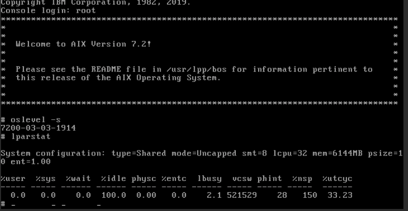
To verify that the VM is working correctly, log into the system using the AIX console.
1.5 - Capturing and exporting a virtual machine
Virtual machine (VM) instances can be captured and exported from the IBM Power for Google Cloud Platform (IP4G) service. This can be done through either the command line interface (CLI) or web interface. The captured image is stored as a new volume on the back end storage. A captured image can then be exported to Google Cloud Storage. Images are exported in an Open Virtualization Appliance (OVA) file. OVA files are compressed using gzip before export to Google Cloud Storage.
When capturing an image, an export destination of “image catalog” and/or “cloud storage” can be selected. The image catalog resides in the customer’s IP4G storage area. It can be used as a template to create new VMs. The cloud storage option transfers the image to Google Cloud Storage immediately. Images in the image catalog are transferrable to cloud storage at a later date as well.
Only one Image Capture and Export or Import function can be performed at a time.
Flush file system buffers to disk
Images captured from running VMs will be captured in a “crash-consistent” state. For best results, when possible, capture images with the VM shut down. If a VM cannot be stopped before capture, it is recommended to flush the file system buffer cache to disk. Use the following commands to accomplish this:
- IBM i: Use the following command to flush all buffers to disk. Do this prior to capturing the image to ensure data integrity.
CHGASPACTOPTION(*FRCWRT)
- AIX or Linux: Use the following command to flush file system bufers to disk:
sync; sync; sync
Performing capture and export via the IP4G user interface
Use the following steps to perform a capture and export through the IP4G interface.
- Navigate to the IP4G Console. Select the desired virtual machine to capture.
- Select the Capture and Export icon in virtual machine instance view. The icon appears in the upper left corner.
- All volumes for the virtual machine are automatically captured by default.
- Determine where the volume backed image or OVA will be exported. Either: image catalog, Cloud Storage, or both.
- Provide the captured image a Name.
- Optional: when exporting to Cloud Storage, specify the following additional parameters:
- Bucket name and any optional folders.
- Access and Secret Keys.
- Select Capture and export.
- After a successful capture or export, a confirmation message is displayed. It will read “When large volumes (in size and/or quantity) are selected, export processing may take a significantly long period of time to complete.”
- Find the newly exported image by completing either one of the following tasks:
- If Cloud Storage was selected for the export, navigate to the Cloud Storage bucket in GCP.
- If image catalog was selected for the export, navigate to Boot images in the IP4G user interface.
- Optional: volume backed images in image catalogs can also be exported to Cloud Storage. After choosing the desired Boot Image, select the Export function on the top of the screen.
Performing capture and export using the pcloud CLI
The pcloud CLI can also be used to capture and export a virtual machine image.
The pcloud compute instances capture command can be used to capture a virtual machine image. The image can be exported to an image catalog, Cloud Object Storage, or both.
Capture VM Instance to image catalog:
pcloud compute instances capture <InstanceName> --destination image-catalog --name <ImageName>
Capture VM Instance to Google Cloud Storage:
pcloud compute instances capture <InstanceName> --destination [cloud-storage|both]
--name <ImageName> --bucketname <Bucket> --accesskey <AccessKey> --secretkey <SecretKey> [flags]
Use the following command to view exported images in the image catalog:
pcloud compute images list
2 - Oracle on IP4G
Guidance for deploying and managing Oracle workloads on IBM Power for Google Cloud.
Overview
IBM Power for Google Cloud (IP4G) provides a robust platform for running mission-critical Oracle database workloads.
IP4G hardware supports various Oracle configurations, including single-instance databases and Oracle Real Application Clusters (RAC).
Key Features
- High Performance: Run Oracle on IBM Power Systems servers optimized for data-intensive workloads.
- Scalability: Easily scale compute and storage resources to meet changing demands.
- Integration: Connect your Oracle databases to Google Cloud services like BigQuery and Looker via low-latency Private Services Access.
Configuration Guides
For detailed instructions on configuring specific Oracle environments, refer to the following guides:
2.1 - Configuring Oracle RAC on IP4G
Configure AIX environments on IBM Power for Google Cloud (IP4G) to support Oracle database installations, including Real Application Clusters (RAC).
Overview
When migrating Oracle RAC to IP4G, you may need to adjust network interface ordering and storage device configuration to match the environment requirements.
Prerequisites
- Root access to the AIX Virtual Machine (VM).
- Familiarity with AIX system administration tools (
smitty,chdev,rendev).
Network Interface Configuration
IP4G VMs assign eth0 for the customer IP address and eth1 for the Resource Monitoring and Control (RMC) interface. Default Oracle RAC configurations may require specific interface ordering which can cause conflicts.
Resolving Interface Conflicts
Choose one of the following methods to resolve interface ordering issues:
- Reconfigure RAC: Update your Oracle RAC configuration to use the Ethernet interfaces in the order they are detected by AIX.
- Rename Interfaces: Use the
rendevcommand to rename Ethernet interfaces to the order expected by your RAC configuration.
Storage Volume Configuration
Storage volumes (hdisks) on IP4G may be detected in a different order than on-premises environments, and will appear as new devices.
Managing Storage Volumes
Resolve Ordering Conflicts:
- Use
rendevto renamehdisksto match your expected layout. - Alternatively, configure Oracle RAC to use the
hdiskidentifiers as detected by the system.
- Use
Update Permissions:
- Because
hdisksare detected as new devices, you must reset ownership and permissions (e.g.,chown oracle:dba /dev/rhdisk*) to allow Oracle access.
- Because
3 - AIX How-To Documents
3.1 - Preparing systems for migration
Use the following prerequisites and recommendations to ensure a successful migration to IBM Power for Google Cloud (IP4G).
For AIX systems, ensure that the operating systems are running the following minimum versions:
| AIX Version | Minimum TL/ML | Notes |
|---|---|---|
| 5.3 | 5300-12-04 | Only supported within a Versioned WPAR |
| 7.1 | 7100-05-06 | |
| 7.2 | 7200-05-01 | |
| 7.3 | 7300-00-01 |
Additional software requirements:
- The devices.fcp.disk.ibm.mpio package must not be installed. Uninstall it if necessary.
Additional recommendations:
- Install cloud-init. This can be done using dnf, yum, or RPM. There are several prerequisites to install for cloud-init. The cloud-init software package is required to leverage some features. Those features include:
- Image capture and deploy.
- Automatic configuration of IP addresses, through the IP4G interface.
- Update MPIO settings for each disk to set algorithm to shortest_queue or round_robin:
chdev -P -l hdiskX -a algorithm=shortest_queue -a reserve_policy=no_reserve - Reboot for the attribute changes to take effect.
3.2 - Migrating to IP4G using a mksysb and alt_disk_mksysb
Use a mksysb from an existing system to migrate into IP4G. Do this by building a new system from a stock image, and using the alt_disk_mksysb command. The following steps highlight how to do so using the pcloud CLI. However, the IP4G specific steps can also be performed from the GUI.
Capturing a Source System mksysb
First, check if the fileset devices.fcp.disk.ibm.mpio exists. To do this, execute the following:
lslpp -Lc | grep devices.fcp.disk.ibm.mpio
If the fileset is installed, there are two ways to handle this. Either it must be removed from the system before the mksysb is created, or when running alt_disk_mksysb. Doing that will involve using the alt_rootvg_op command to wake the alt disk and remove the fileset.
Customers are responsible for evaluating the impact of removing the fileset in their environment.
To remove execute:
installp -u devices.fcp.disk.ibm.mpio
To begin, take a mksysb on the source system. It is recommended that the rootvg of the source system is not mirrored. If it is, edit the image.data file to unmirror it before restoring it. Details for that are included below. If the source system is running AIX 7.2 or higher, using the following command:
mksysb -C -i /path/to/hostname.mksysb
If the source system is running AIX 7.1, use the following command:
mksysb -i /path/to/hostname.mksysb
Build the target system
Build the system to do the alt_disk_mksysb on. This system will boot at first from a stock AIX image. Then after the mksysb restore, it will boot from the restored AIX image. If a stock image has not already been imported, see Obtaining a VM Image
LINK
To get started, gather the following information:
- Use a hostname that will be the final hostname in IP4G.
- Use a stock image that most closely matches the source system. Later TL/SP levels are OK.
- Use the desired CPU, Memory, CPU Type, and Network settings for the final host to have.
Example:
pcloud compute instances create hostname –image AIX-7200-05-09 –network gcp-network -c 0.25 -m 8 -t shared
Add disks to the target system
Two disks are needed. One for temporary storage for the mksysb. The other for restoring the mksysb to alt_disk_mksysb. Wait for the new instance to build.
First, build the target disk for the mksysb. It needs to be large enough to hold the source system rootvg. Change the size and disk type appropriately for the system.
pcloud compute volumes create hostname-rootvg -s 20 -T ssdLog into the new target system from the console as root. Then, run cfgmgr to discover the new disk. There should now be two disks: hdisk0, the original stock AIX image disk, and hdisk1, the target disk for the mksysb. One more disk is needed to hold the mksysb to restore. The easiest to cleanup is to add it to the rootvg, and expand /tmp.
Use the pcloud command to create a new disk, changing the size to be sufficient for holding the mksysb:
pcloud compute volumes create hostname-tempdisk -s 20 -T ssdLog into the target system, and discover the new disk with cfgmgr. The new disk should be hdisk2. To validate which is which, run:
lsmpio -qaAdd the disk to the rootvg. Note that it is important to only add the temporary disk here:
extendvg rootvg hdisk2.Add space to /tmp
chfs -a size=+20G /tmp
Restore the mksysb on the target system
Use the following to restore the mksysb on a target system.
Copy the mksysb file from the original source system to the new target system.
Place it in /tmp. Use any preferred method, such as scp, for transferring the mksysb. Note that if the original rootvg was mirrored, unmirror it before using alt_disk_mksysb. Do this by restoring the image.data file and editing it. It must be edited so the PPs line for each LV is equal to the LPs line. To restore image.data, use this command:
restore -xqvf /tmp/hostname.mksysb ./image.dataIf this had to be done, specify to use the new image.data when restoring. Add the flag -i /tmp/image.data to the alt_disk_mksysb command.
To restore the mksysb use the alt_disk_mksysb command:
alt_disk_mksysb -m /tmp/hostname.mksysb -d hdisk1 -z -c /dev/vty0- This will automatically set the bootlist to boot off of the new volume, hdisk1.
- Reboot:
shutdown -Fr
Confirm the VM has booted from the disk containing the restored mksysb. In this example, that would be hdisk1. Use lspv to validate which disks / vg’s are present:
lspv
Clean up the temporary disks
Use the following to clean up the temporary disks.
Use exportvg to remove the old rootvg exportvg old_rootvg rmdev -dl hdisk0.
rmdev -dl hdisk2Use the pcloud command to set the new rootvg volume as bootable:
pcloud compute volumes update hostname-rootvg --bootable yesUse the pcloud command to clean up the old hdisks. Find the old boot disk name using:
pcloud compute instances describe hostname
Set the old disk as not bootable
Set the old disk so it is not bootable. Match the name to the boot-0 volume from the instances describe output. To do this use:
pcloud compute volumes update hostname-d4751509-00000b25-boot-0 --bootable no
Delete the original boot volume and the temporary disks
Use the following to delete the original boot volume, and the temporary disks.
pcloud compute volumes delete hostname-d4751509-00000b25-boot-0

pcloud compute volumes delete hostname-tempdisk
3.3 - AIX MPIO Recommendations
This document provides AIX Multipath I/O (MPIO) best practices for IBM Power for Google (IP4G) block storage.
Recommended MPIO Configuration for AIX
The following AIX Multipath I/O (MPIO) settings have been validated by the IBM Power for Google Cloud engineering team to provide the best mix of performance and stability. If you feel your workload requires an alternative configuration, please contact IBM Power for Google Cloud support before making changes.
| Attribute | Recommended Value | Motivation |
|---|---|---|
algorithm | shortest_queue | Dynamically checks the pending I/O load on every available path before sending data, ensuring traffic is always routed to the least busy path. |
reserve_policy | no_reserve | Prevents the host from locking the disk exclusively. This is required for IBM Power for Google Cloud non-disruptive maintenance using Live Partition Mobility (LPM). |
hcheck_interval | 60 | Tells AIX to check failed paths every 60 seconds. If set to 0 (default), a failed path might never automatically come back online. |
hcheck_mode | nonactive | Checks only paths that have no active I/O, minimizing overhead. |
queue_depth | 32 | This setting maximizes throughput (IOPS) while maintaining consistent low latency. Please contact support if you feel your workload requires a different setting. |
Verify AIX MPIO Configuration
Check existing MPIO configuration for each disk using lsattr -El <disk_name> and filtering for the attributes shown in the table above. This should be done for each disk in the operating system.
# lsattr -El hdisk0 | egrep "algorithm|reserve_policy|hcheck_interval|hcheck_mode|queue_depth"
algorithm       shortest_queue                                      Algorithm                    True+
hcheck_interval 60                                                  Health Check Interval        True+
hcheck_mode     nonactive                                           Health Check Mode            True+
queue_depth     32                                                  Queue DEPTH                  True+
reserve_policy  no_reserve                                          Reserve Policy               True+
Set AIX MPIO Configuration for Existing Disks
If you have existing disks that need to be updated with the recommended MPIO settings, you can use the following commands:
# Set algorithm to shortest_queue
chdev -l <disk_name> -a algorithm=shortest_queue

# Set reserve_policy to no_reserve
chdev -l <disk_name> -a reserve_policy=no_reserve

# Set hcheck_interval to 60
chdev -l <disk_name> -a hcheck_interval=60

# Set hcheck_mode to nonactive
chdev -l <disk_name> -a hcheck_mode=nonactive

# Set queue_depth to 32
chdev -l <disk_name> -a queue_depth=32
Set AIX MPIO Configuration for New Disks
These commands update the Predefined Attribute (PdAt) database so that any future disk you map or discover will automatically inherit the best practices settings without manual intervention.
# Set default algorithm to shortest_queue
chdef -a algorithm=shortest_queue -c disk -s fcp -t mpioosdisk

# Set default reserve_policy to no_reserve (Critical for LPM)
chdef -a reserve_policy=no_reserve -c disk -s fcp -t mpioosdisk

# Set default health check interval to 60 seconds
chdef -a hcheck_interval=60 -c disk -s fcp -t mpioosdisk

# Set default health check mode to nonactive
chdef -a hcheck_mode=nonactive -c disk -s fcp -t mpioosdisk

# Set default queue_depth to 32
chdef -a queue_depth=32 -c disk -s fcp -t mpioosdisk
Monitoring Available Paths in AIX
Each disk attached to an IBM Power for Google Cloud block storage volume will have four fiber channel paths. These paths are distributed across a fully redundant dataplane, and a dual fiber channel fabric. A disk can lose up to 3 of 4 fiber channel paths and still remain operational.
Customers should monitor the status of MPIO paths. While path failures are expected during maintenance events, it is important to evaluate any path failure that is unexpected.
Display path status for all devices.
lspath
Display all paths associated with a specific device, including their status (Available, Defined, Failed).
lspath -l <device_name>
This command shows detailed information and status for all devices and paths, including their status and path status.
lsmpio
This command provides detailed information for a specific device.
lsmpio -l <device_name>
Scheduled Maintenance and AIX Path Recovery
IBM Power for Google Cloud performs storage maintenance to maintain the health of the storage system. During maintenance events, some paths may go down but should be automatically recovered. Review the following actions that should be taken before and after maintenance events. These actions and any additional actions are always included in maintenance notifications as well.
Before Maintenance:
Check Path Status: Use lspath or lsmpio to get a baseline of current path status. This will help identify any discrepancies after maintenance.
Resolve any Down Paths: If paths are discovered as down they should be fixed prior to maintenance to avoid an outage. A standard method for doing so is to:
- Find the failed paths using lspath, note the hdisk and fscsi device
- Remove the failed paths using
rmpath -l hdiskX -p fscsiY - Rediscover all paths using cfgmgr
- Use lspath to verify the path state
After Maintenance:
Verify Path Status: Use lspath or lsmpio again to confirm that all paths have recovered and are in the “Available” state.
Recover Paths: Sometimes AIX does not automatically recover paths. During these scenarios, customer should attempt to recover the paths. A standard method for doing so is to:
- Find the failed paths using lspath, note the hdisk and fscsi device
- Remove the failed paths using
rmpath -l hdiskX -p fscsiY - Rediscover all paths using cfgmgr
- Use lspath to verify the path state
Report Issues: If there are any issues with pathing or storage connectivity after maintenance, promptly report them to Converge for resolution.
By following these guidelines and proactively monitoring MPIO paths, customers can ensure the high availability and performance of their applications running on IBM Power for Google.
Additional Resources
You can learn more about the general MPIO configuration from the official IBM documentation:
It is important customers understand their Application and select MPIO policies that best suit their Application requirements.
3.4 - AIX TCP/IP Settings
Optimizing TCP/IP Settings for Improved Network Performance in IP4G
This document provides guidance on adjusting TCP/IP settings in your IP4G environment within Google Cloud to potentially enhance network performance. These settings are intended as starting points and may require further tuning based on the specific needs of your applications and virtual machines.
Note: Before making any changes, ensure you have a baseline understanding of your current network performance. This will help you assess the impact of any adjustments made.
Recommended TCP/IP Settings
The following commands can be used to modify the TCP/IP settings:
chdev -l en0 -a tcp_sendspace=2049152
chdev -l en0 -a tcp_recvspace=2049152
chdev -l en0 -a rfc1323=1
chdev -l en0 -a mtu=1440
no -p -o sb_max=8196608
no -p -o tcp_nodelayack=0
no -p -o sack=1
chdev -l en0 -a mtu_bypass=on
no -p -o tcp_sendspace=2049152
no -p -o tcp_recvspace=2049152
Explanation of Settings
- tcp_sendspace & tcp_recvspace: These settings control the send and receive buffer sizes for TCP connections. Increasing these values can improve performance, especially for high-bandwidth connections.
- rfc1323: Enables TCP extensions defined in RFC 1323, including Timestamps and Window Scaling, which can improve performance on high-latency connections.
- mtu: Sets the Maximum Transmission Unit (MTU) size. This value determines the largest packet size that can be transmitted over a network. A Google Cloud Network VPC default MTU is 1460 bytes. While you can adjust this to a value between 1300 and 8896 bytes (inclusive), it’s generally recommended to keep the Google Cloud VPC Network MTU at 1460 to ensure compatibility within the Google Cloud environment and avoid potential fragmentation issues. If your Google Cloud Network VPC is configured with a custom MTU, ensure the
mtusetting on your IP4G instances matches the VPC MTU. If you configure your Google Cloud Network VPC to use an MTU other than 1460, contact IP4G Support. If your GCP VPC is at the default 1460 MTU, your IP4G AIX instances should use an MTU of 1440. - sb_max: Sets the maximum socket buffer size. Increasing this value can improve performance for applications that utilize large socket buffers.
- tcp_nodelayack: Disables the Nagle algorithm, which can improve performance for certain applications by reducing latency. However, it may increase network overhead.
- sack: Enables Selective Acknowledgment (SACK), which can improve performance in the presence of packet loss.
- mtu_bypass: Allows packets larger than the MTU to be sent to other VMs on the same frame/vswitch, improving performance for communication between VMs on the same frame.
Evaluating the Results
After implementing these settings, it’s essential to monitor your network performance to determine their effectiveness. Several tools can assist in this evaluation:
- Network Monitoring Tools: Utilize tools like
netstat,tcpdump, orWiresharkto monitor network traffic and identify any bottlenecks or performance issues. - Performance Benchmarking Tools: Employ tools like
iperf3to measure network throughput and latency before and after applying the settings. - Application-Specific Monitoring: Monitor the performance of your applications to assess the impact of the TCP/IP adjustments on their behavior.
Remember: These settings are starting points, and further adjustments may be necessary based on your specific environment and application requirements. Continuously monitor and fine-tune these settings to optimize your network performance.
Additional Considerations
- Google Cloud Network Infrastructure: When adjusting TCP/IP settings, consider the characteristics of your Google Cloud Virtual Private Cloud (VPC) network. Factors like the configured MTU (typically 1460 bytes), subnets, firewall rules, and any network virtualization layers can influence network performance. Ensure your settings are compatible with your VPC configuration and don’t introduce unintended bottlenecks.
- Application Requirements: Different applications have varying network performance needs. Research and understand the specific requirements of your applications to fine-tune the settings accordingly. For example, applications sensitive to latency might benefit from disabling
tcp_nodelayack, while those prioritizing throughput might benefit from larger send and receive buffers. - Virtual Machine Configuration: If you’re running virtual machines on Compute Engine, ensure the virtual network interfaces are configured correctly. Verify that the machine type provides sufficient network bandwidth and that no resource limitations on the VM instance are hindering network performance.
By carefully adjusting and monitoring your TCP/IP settings, you can potentially enhance the performance of your IP4G environment and ensure optimal network efficiency for your applications.
3.5 - Install gcloud SDK on AIX
Installing the gcloud sdk on AIX will allow you to download and upload from Google Cloud Storage buckets, as well as controlling other aspects of your google cloud environment. In AIX, it is primarily used for interacting with Storage Buckets and objects.
This Guide is not comprehensive, as covering all AIX versions and types is not possible. Note that it is easiest on AIX 7.3, as it requires python 3.8 or above. This example assumes a system built by downloading the AIX 7.3 TL1 stock image.
First, prepare your filesystems for new content
chfs -a size=+2G /opt
chfs -a size=+500M /tmp
chfs -a size=+500M /var
Next, I recommend you update your system using SUMA. To do this, we’ll clear out /usr/sys/inst.images first
rm -rf /usr/sys/inst.images/*
smitty suma
Select Download Updates Now (Easy)
Select Download All Latest Fixes
Once those have downloaded, update your system using
smitty update_all
For the directory, enter /usr/sys/inst.images
Change ACCEPT new license agreements? to yes
Once those updates have installed run
updtvpkg
dnf update python3 dnf
You should now be ready to install requisite software for the gcloud sdk
dnf install curl coreutils tar git bash python3-pip
Change your path to use the new gnu utilities
export PATH=/opt/freeware/bin:$PATH
Download the gcloud sdk installer and run it
curl https://sdk.cloud.google.com | bash
For an installation directory use /opt/freeware/
For Do you want to help improve the Google Cloud CLI (y/N)? say n
You will now see:
ERROR: (gcloud.components.update) The following components are unknown [gcloud-crc32c].
You can disregard this. You may wish to switch to a non-root user for the remaining steps.
Set your path
export PATH=/opt/freeware/google-cloud-sdk/bin/:$PATH:/opt/freeware/bin
Now you can run the google cloud sdk:
gcloud auth login
Follow the login prompts, pasting in the code to authenticate.
Adjust your crc settings. Using if_fast_else_skip is faster and uses less CPU, but also does no crc checking.
gcloud config set storage/check_hashes if_fast_else_skip
or
gcloud config set storage/check_hashes always
You should now be able to list the content of buckets you have access to, and download files.
gcloud storage ls gs://<bucketname>
gcloud storage cp gs://<bucketname>/<filename> /path/to/download/
3.6 - RMC details and troubleshooting
This article provides details on Resource Monitoring and Control (RMC). Also presented below are troubleshooting methods for common problems.
Use the methods below to address issues. If these methods do not resolve the issue, please Create a Support Ticket.
RMC details and troubleshooting
This article provides details on Resource Monitoring and Control (RMC). Also presented below are troubleshooting methods for common problems.
What is RMC?
Management consoles use RMC to perform dynamic operations on a virtual machine (VM). RMC connections are routed through a dedicated internal virtual network using IPv6. That network’s configuration prevents a VM from communicating with another VM.
How to troubleshoot RMC
The methods below can help troubleshoot common problems with RMC. Most common is a VM cannot be modified online and is in an unhealthy state. In the example below, the Health of the virtual machine is listed as “Warning”.
$ pcloud compute instances list
InstanceID                            Name             Status   Health   IPs
12345678-9abc-123a-b456-789abcdef123  lpar1            ACTIVE   WARNING  [192.168.1.5]
Restart RMC
Restarting RMC is the most common solution.
/usr/sbin/rsct/bin/rmcctrl -z
/usr/sbin/rsct/bin/rmcctrl -A
/usr/sbin/rsct/bin/rmcctrl -p
Be aware that layered software using Reliable Scalable Cluster Technology (RSCT) will be impacted. For example, this will trigger an immediate failover in PowerHA environments.
Validate RSCT version
Validate the version of the RSCT. Methods for this depend on the operating system. The RSCT packages must be at version 3.2.1.0 or later.
- AIX
lslpp -L rsct.*
- RedHat
rpm -qa | grep -e rsct -e src
Gathering RMC information
Use the following to gather information about the RMC. This information can be helpful in resolving many issues.
/usr/sbin/rsct/bin/lsnodeid
lsrsrc IBM.MCP
/opt/rsct/bin/rmcdomainstatus -s ctrmc
Validating Connectivity
Validate the connectivity by using the methods below.
- Verify that the en1 interface has an IPv6 address beginning with fe80::
- For AIX use:
netstat -in
Make sure the following lines are uncommented in /etc/rc.tcpip:# netstat -in Name Mtu Network Address Ipkts Ierrs Opkts Oerrs Coll ... en1 1500 fe80::ecad:f1ff:febe:ea13 711114 0 711198 0 0 ...Then, execute the following:start /usr/sbin/autoconf6 "" " -i en1" start /usr/sbin/ndpd-host "$src_running"autoconf6 -i en1 - For Linux use:
ip addr show
- For AIX use:
- Get the HMC or Novalink IPv6 address from the virtual machine. Use this command:
lsrsrc IBM.MCP - Ping the IPv6 address. If the ping fails, please escalate to support.
- Telnet ipv6_address 657. If a ping is successful, but telnet fails to connect, there may be a firewall issue.
Verify the services are active
Use the following command to verify if the services are active.
lssrc -s ndpd-host
If it isn’t active, use the following:
startsrc -s ndpd-host
3.7 - RMC and AIX 6.1
Reliable Scalable Cluster Technology (RMC) is essential for performing Live Partition Mobility (LPM) and Dynamic Logical Partitioning (DLPAR) operations on IBM Power for Google Cloud (IP4G). To establish a working RMC connection on an AIX 6.1 virtual machine, you must install updated Reliable Scalable Cluster Technology (RSCT) packages. This guide describes the requirements and procedures for restoring RMC functionality on AIX 6.1 VMs.
Prerequisites and Limitations
AIX 6.1 is an unsupported operating system. Using AIX 6.1 VMs in IP4G involves the following limitations and risks:
- Production Use: AIX 6.1 is not recommended for production environments because it lacks ongoing support, security fixes, and validation and has been out of support since April 30, 2017.
- Stability: Platform updates and maintenance activities may impact VM stability or manageability.
- Compute Hosts: AIX 6.1 VMs only boot on Power9 compute hosts, which are available in limited regions.
- Maintenance: If LPM fails during host maintenance, the VM will shut down automatically to allow maintenance to proceed.
- Support: Support requests for AIX 6.1 are handled as Priority 4 (P4) with reasonable-effort support only. No AIX-specific support is provided.
Upgrading to a supported AIX release is strongly recommended to ensure stability and compatibility.
Required RSCT Filesets
To restore RMC functionality, obtain the following RSCT filesets from a more recent AIX release, such as AIX 7.1 TL4 (RSCT version 3.2.1.15).
rsct.basicrsct.corersct.compat.basicrsct.compat.clientsrsct.opt.stackdumprsct.opt.storagerm
Installing RSCT Software
Follow these steps to install the updated RSCT filesets.
Obtain the required RSCT filesets from a newer AIX release.
Transfer the filesets to a directory on the AIX 6.1 VM.
Change to the directory containing the filesets.
Install the filesets using one of the following methods:
Using SMIT:
smitty update_allUsing command line:
install_all_updates -d .Using installp:
installp -acgXYd . all
Troubleshooting
If RMC fails to start after installation, verify that the RSCT subsystems are active.
- Check the status of the RMC subsystem:
lssrc -s ctrmc - If the subsystem is not active, attempt to start it:
startsrc -s ctrmc
4 - IBM i How-To Documents
4.1 - Accessing the IBM i Console
This article explains two ways to access the IBM i console. The first method is through the IBM Power for Google Cloud (IP4G) user interface. The second method is through a LAN console.
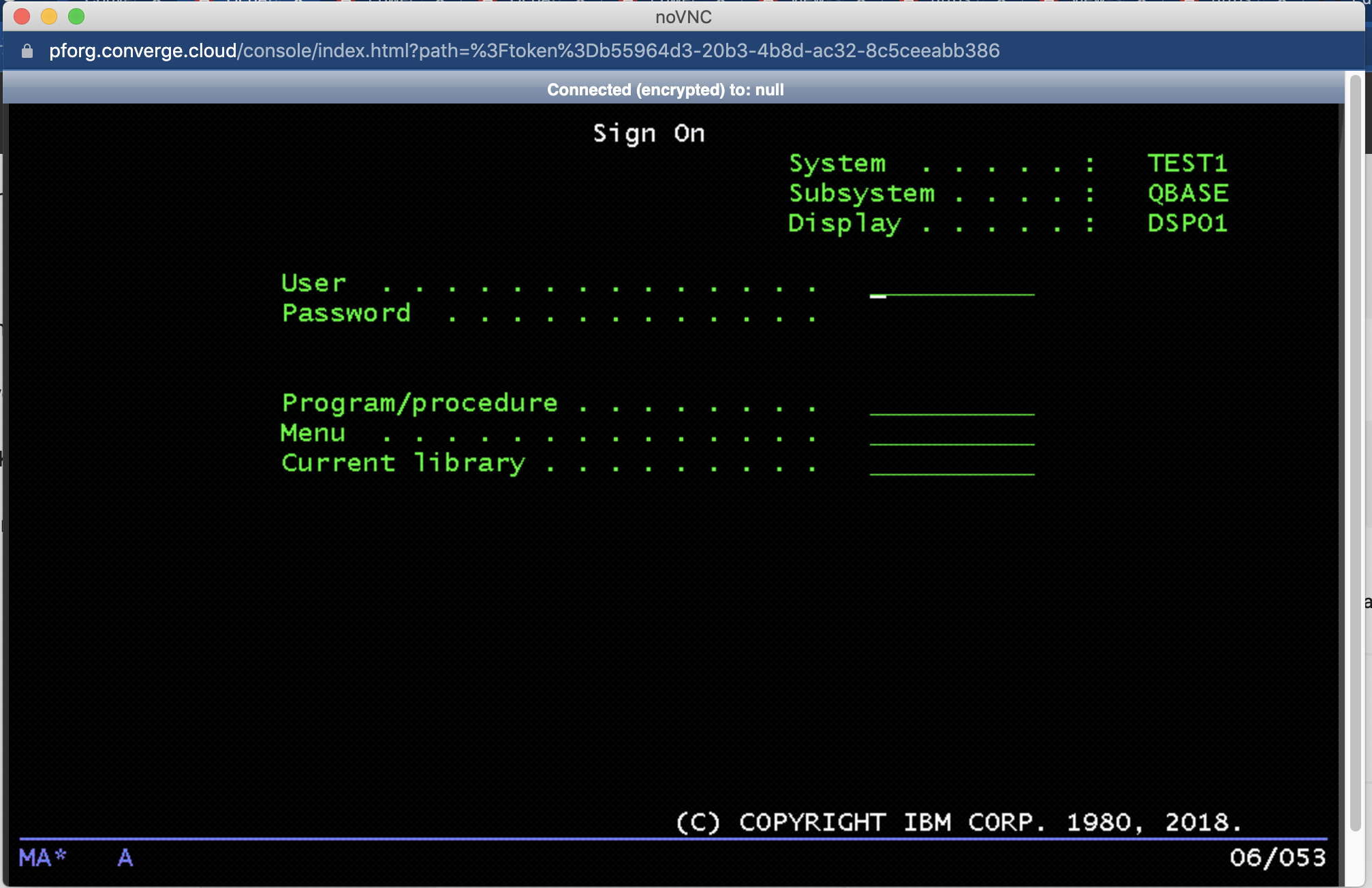
IP4G web console
Browse to an IBM i instance from the VM Instances list. Then, click on the Console button in the actions toolbar:

A VNC window connected to the console session will open.
Use the tool bar at the bottom to access the Extended Function keys, F13 through F24. Some users may need to scroll the VNC window down to see them.

The shift key does not always work for the Extended Function keys. Click the “Next P…” button to display the Extended Function Keys.
The web console will time out occasionally. A session can be re-established by refreshing the IP4G web interface page.
LAN Console
Optionally, set up a LAN console by adding an additional network interface to the Virtual Machine (VM). This can be done via the pcloud command line.
Obtain a list of the available networks:
pcloud compute networks list
NetworkID                             Name                 VLANID
2c45110a-2a33-4880-a90d-000000000000  test-network-1       334
932cda0c-6cc7-4a5a-93f2-000000000000  test-network-2       111
fcc506f3-70e2-45a2-9ee3-000000000000  test-network-3       20
Obtain a list of the available VM instances:
pcloud compute instances list
NetworkID                             Name                 VLANID
...
36e0b4ac-1e63-410d-97f2-000000000000  tst-ibmi72      ACTIVE   OK      [10.3.4.116]
...
Attach a second network interface to the VM. Specify the network name and the VM instance name obtained above.
pcloud compute instances attach-network tst-ibmi72 --network test-network-1
When this command executes, IP4G assigns the network and selects an IP from the pool. Use this IP for the Service Tools LAN Adapter. However, it will need assigned manually. Use the following command to view the new network:
pcloud compute instances describe tst-ibmi72
instanceID: 36e0b4ac-1e63-410d-97f2-000000000000
name: tst-ibmi72
...
systemType: s922
cores: 1
procType: dedicated
memory: 8
pinPolicy: none
status: ACTIVE
...
networks:
- ipAddress: 10.3.4.142
  macAddress: 00:00:00:00:00:00
  networkName: test-network-1
...
Per the example, the new network interface uses the IP address 10.3.4.142.
Use the following command to determine the resource name of the new interface:
WRKHDWRSC *CMN
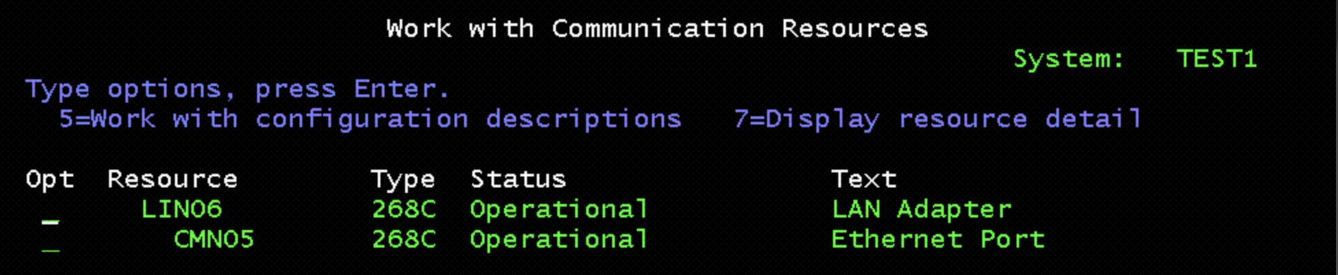
In this example, the new adapter is CMN05. This is the device to use in Service Tools. When added via the pcloud command, cloud-init may create a line description for the new device. Check this with the WRKLIND command. If needed, vary off and delete the new line description if one was created.
Start Service Tools:
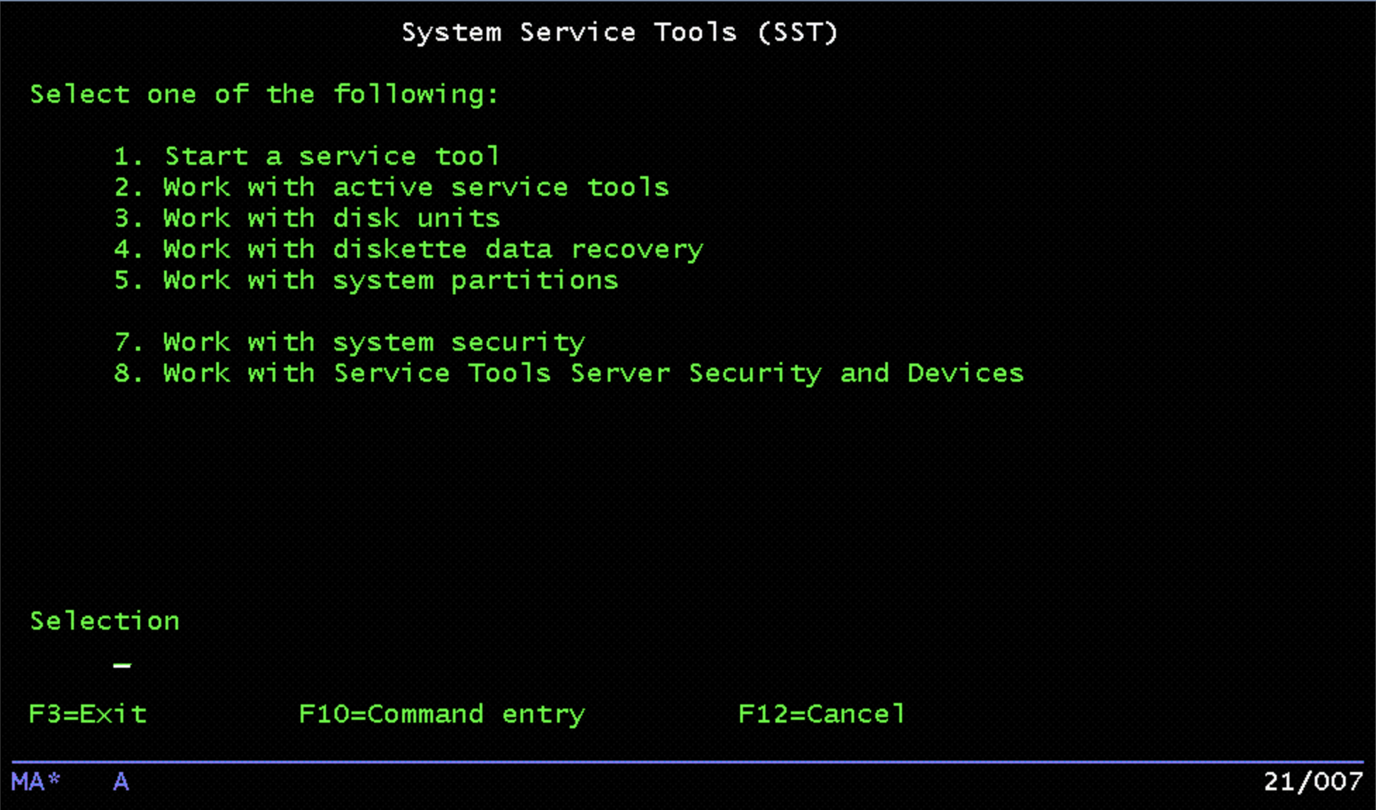
Choose Option 8, “Work with Service Tools Server Security and Devices”:
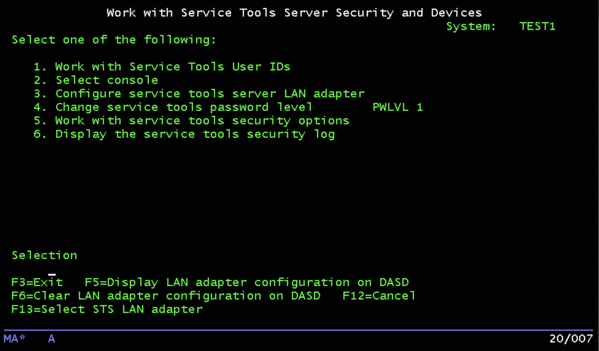
Press F13 (Select STS LAN adapter). A list of the available resources will be displayed:
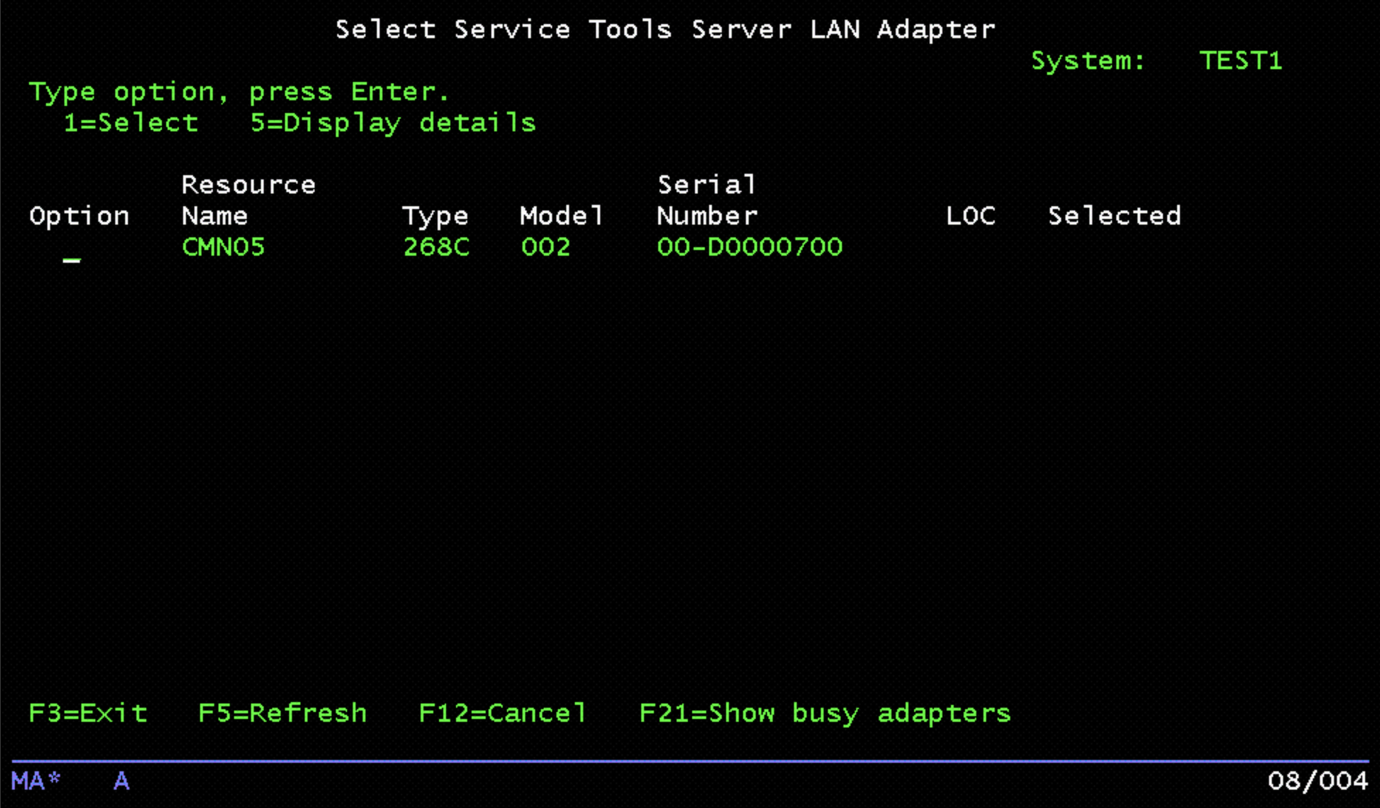
Choose Option 1, then press Enter to go to the configuration panel. Enter the IP address recorded earlier. Then, enter the matching netmask from the IP4G network configuration:
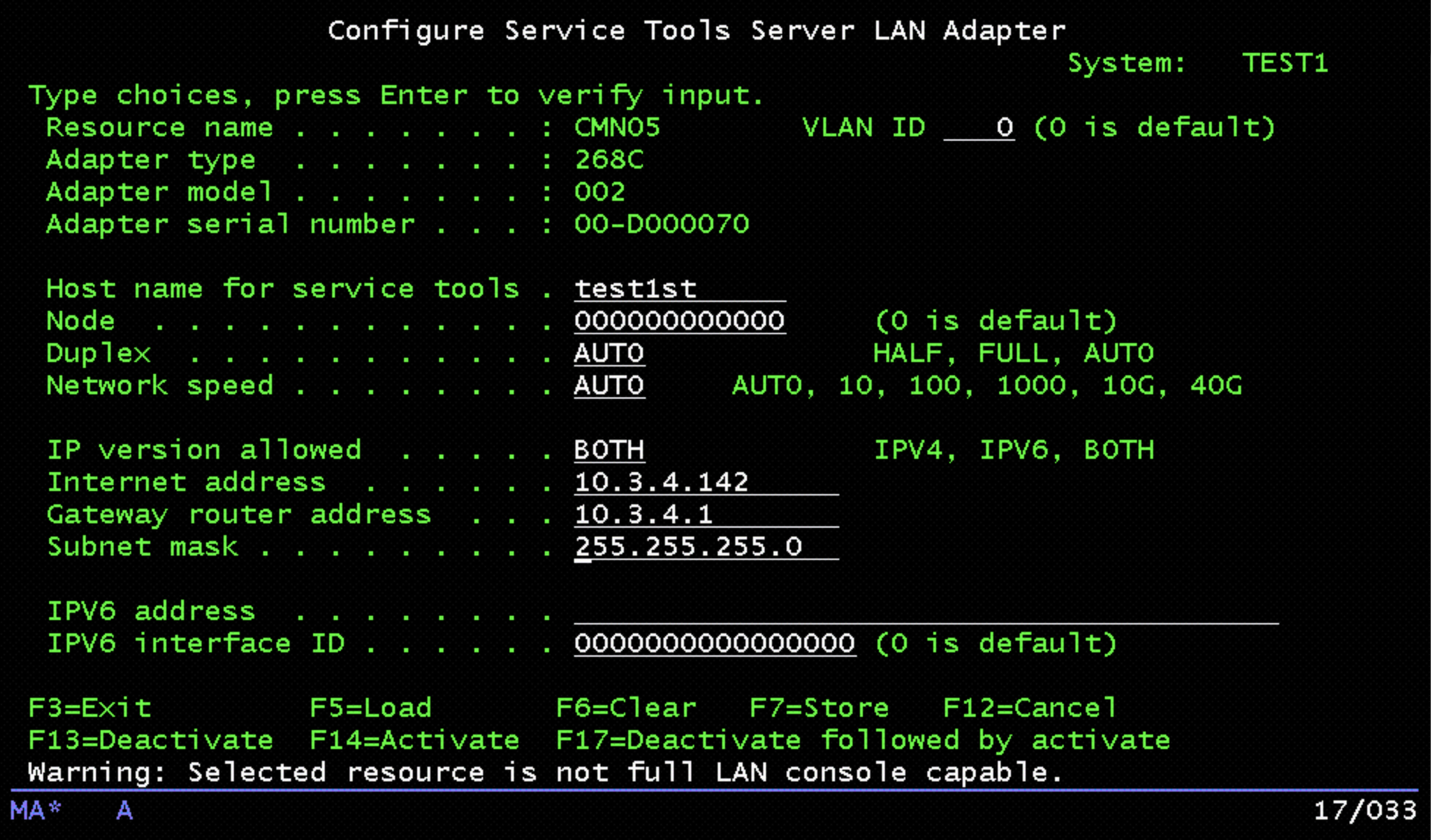
Press F7 to store the configuration. Then press F17 to de-activate/activate the adapter. It should then be possible to ping the IP address of the adapter. Use this as the console address in IBM i Access Client Solutions:
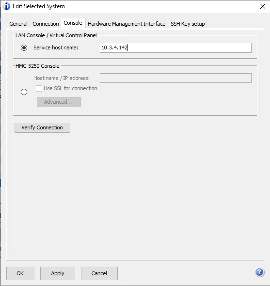
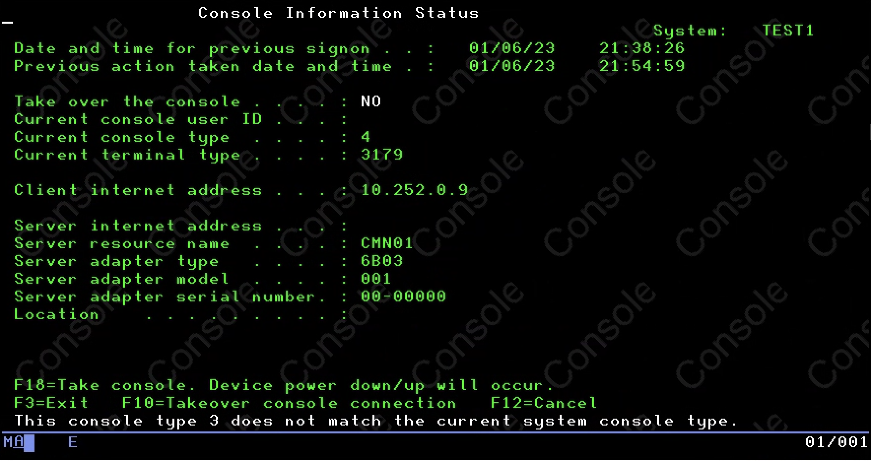
Once configured, use the “5250 Console” link in IBM i Access Client Solutions to access the console. Optionally, take over the console if prompted. Use the default user account to connect. The default user account uses “11111111” as the user name and password. Alternately, use an account created in Service Tools.
4.2 - Accessing IBM i Virtual Machines
This article covers how to access IBM i virtual machines (VMs) in IBM Power for Google Cloud (IP4G). Use the following information to access newly created IBM i virtual machines (VMs). Typically, end-users access IBM i VMs running in IP4G the same way they access IBM i systems running on-premises. Network traffic directed to IP4G VMs normally routes over any of the available connectivity methods. However, if network connectivity has not been completed, use the following procedures to gain access.
Requirements:
- IP connectivity to IP4G VM
- IBM i Access Client Solutions (iACS) installed per IBM Documentation
Configuring port forwarding
Use any 5250 emulator to access IP4G VMs using SSH tunelling to forward port 23. IBM i Access Client Solutions (iACS) requires forwarding several other ports for licensing and other system administrative functions. By default the majority of the required ports are blocked by IP4G and Google Cloud firewalls. Leverage SSH tunneling to forward these ports to a local workstation and gain access.
First, start the required TCP/IP servers on the VM:
- SSH - For remote logins
STRTCPSVR SERVER(*SSH)
- ADMIN HTTP server - IBM i Navigator & Digital Certificate Manager
STRTCPSVR SERVER(*HTTP) HTTPSVR(*ADMIN)
- Telnet - Remote TN5250 sessions
STRTCPSVR SERVER(*TELNET)
The required ports to forward are:
- 23
- 2001
- 2005
- 449
- 8470-8476
Configuring port forwarding under macOS or Linux
If using a Mac or Linux system, use the following command or similar:
ssh -L 50000:localhost:23 -L 2001:localhost:2001 -L 2005:localhost:2005 \
-L 449:localhost:449 -L 8470:localhost:8470 -L 8471:localhost:8471 \
-L 8472:localhost:8472 -L 8473:localhost:8473 -L 8474:localhost:8474 \
-L 8475:localhost:8475 -L 8476:localhost:8476 -o ExitOnForwardFailure=yes \
-o ServerAliveInterval=15 -o ServerAliveCountMax=3 <user>@<ipaddress>
Where <user> is QSECOFR or another user created on the target VM, and
<ipaddress> is the IP address of the IP4G VM.
Configuring port forwarding under Windows using PuTTY
If using a Windows system, you can use the free PuTTY utility.
Launch PuTTY. Under Session, fill in the Host Name (or IP address) field. Use the public IP address of the IBM i VM in IP4G. For Connection type, select SSH.
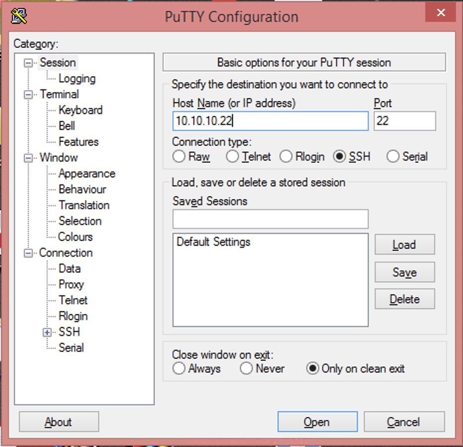
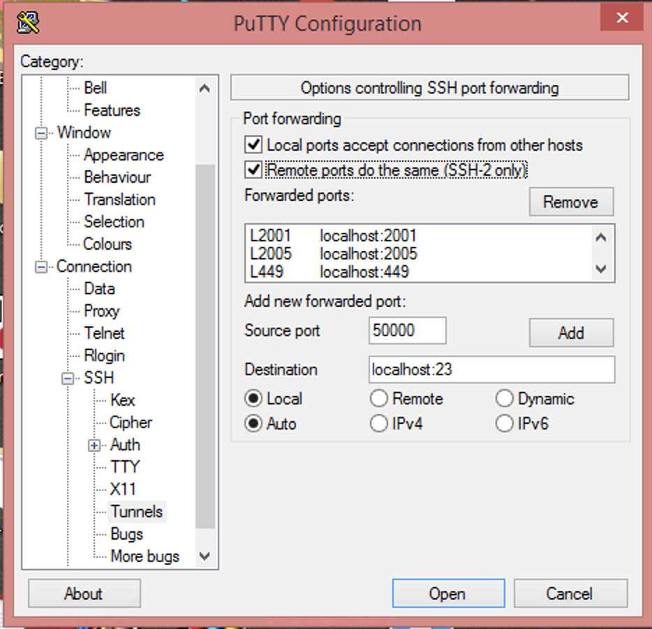
Next, in the left side navigation pane, expand the Connection tree. Then expand the SSH tree. Within that tree, click on Tunnels. On that screen:
- Check “Local ports accept connections from other hosts”
- Check “Remote ports do the same (SSH-2 only)”
Next, add and properly set the ports from the required port list above. Those ports, 23, 2001, 2005, 449, and 8470-8476 each need added. For each port:
- Enter the port number into the Source port field.
- Set Destination to
localhost:. - Click Add.
- Repeat these steps until all of the required ports are added.
- For destination port 23, the Source port should be set to
50000.
Click on Session in the left navigation window. Give the just completed configuration a name, and click Save. This will prevent having to perform the previous steps again for this VM.
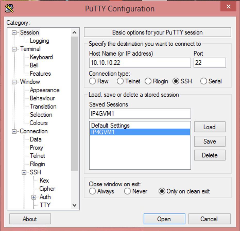
At the bottom of the PuTTY Configuration window, click Open. This starts the PuTTY session and begins port forwarding. A prompt to accept the remote system key on first use will appear. Click Accept. Then, log in using QSECOFR or another configured user.
Configuring iACS to use forwarded ports
Next, configure iACS to use forwarded ports. Do this only after port forwarding has been configured and started.
Create a new 5250 session in iACS.
- Use localhost, or 127.0.0.1 for the destination address.
- Set the Destination Port to 50000.
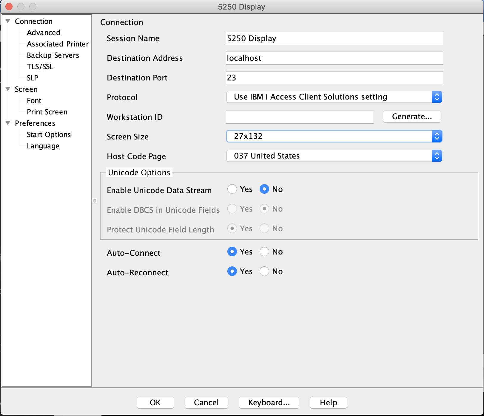
Click OK and connect to the system.
Additionally, IBM i Navigator can be accessed through the following URL:
4.3 - Preparing systems for migration
Use the following prerequisites and recommendations to ensure a successful migration to IBM Power for Google Cloud (IP4G).
For IBM i systems, ensure that the operating systems are running the following minimum versions:
| IBM i version | Minimum PTF Level | Notes |
|---|---|---|
| 7.2 | TR8 | Only on Power 9 systems. 7.2 has been withdrawn from support. |
| 7.3 | TR12 | |
| 7.4 | TR6 | |
| 7.5 | Supported in base release. |
Additional software requirements:
- Ensure PASE and Open Source environment is installed and boostrapped.
- Ensure cloud-init is installed. It is required to support IBM i OS licensing functions. Be aware, there are several prerequisites to install for cloud-init.
Additional recommendations:
- If possible, ensure that source systems have the latest PTF kit for their OS level installed.
- If possible, ensure that all PTFs required for iSCSI VTL connectivity are installed. See the following site for a list of specific PTFs: (https://www.ibm.com/support/pages/ibm-i-removable-media-support-iscsi-vtl)
4.4 - Configuring an IBM i Virtual Machine Instance
Storage volumes and Operating Systems
The number of storage volumes per VM varies by Operating System. IBM i 7.2, and later operating systems, support 127 storage volumes. Operating systems earlier than IBM i 7.2 support 64 storage volumes.
Accessing the IBM i console
For information about accessing the IBM i console, see Accessing the IBM i Console.
Tips for working with the IBM i console:
- The default IBM i user and password are QSECOFR and QSECOFR, respectively.
- When the VM is first provisioned, cloud-init will be executed. This will create two interfaces that IP4G will use to configure the IP address and inject license keys. Do not restart the system until cloud-init has finished and the VM is available on the network, you should see that the VM health status is ‘OK’ and you can access the console and see the initial ibmi screen. If cloud-init is interrupted, a support case must be opened to run the initial provisioning again, or delete and recreate the VM.
Licensing information
License keys are injected automatically during the provisioning process via cloud-init. Upon first login, the license agreements will need to be accepted.
For more information about minimum supported OS version and PTF levels, see Preparing systems for migration.
After deploying an IBM i VM, accept the license agreements. To accept the license agreements from the console, Select all with a 5 next to each license agreement. Click “Next…” and PF15 to show more items. After accepting the license agreements, press PF3. Then, wait until cloud-init configures the network and injects license keys.
Verifying the cloud-init configuration
The cloud-init configuration process can take up to five minutes. Do not restart the VM while cloud-init is executing, you should see that the VM health status is ‘OK’. If the VM is restarted during this time, support must be contacted. They will have to manually configure network and license keys.
Use the CFGTCP command to verify cloud-init correctly configured TCP/IP addresses. Enter the command, then choose Option 1. Verify the IP addresses match the VM’s internal IP addresses.
The example image below shows the Work with TCP/IP Interfaces window.

If the external IP address is not displayed, wait approximately ten minutes. Then, refresh the terminal. Ping the external TCP/IP address. The external address must match what is shown in the IP4G user interface under VM Instances –> <server name>. Contact support or delete and reprovision the IBM i VM if the system cannot be reached.
Changing the default passwords
The System Service Tools (SST) and Dedicated Service Tools (DST) passwords are set to QSECOFR/QSECOFR. Service Tools access will be required to configure any newly-atttached disks. To change the System Service Tools (SST) and Dedicated Service Tools (DST) passwords complete the following steps.
- Enter the STRSST command.
- At the SST login screen, log in using QSECOFR/QSECOFR. Change the password if prompted.
- Use the SST functions to add additional disks to any ASP configuration.
5 - Linux How-To Documents
5.1 - Preparing systems for migration
Use the following prerequisites and recommendations to ensure a successful migration to IBM Power for Google Cloud (IP4G).
For Power Linux systems, ensure that the operating systems are running the following minimum versions:
| Linux Distribution | Minimum Release | Notes |
|---|---|---|
| Red Hat Enterprise Linux | 8.4 for Power LE | Earlier releases might run on Power 9 systems only |
| 9.0 for Power LE | Earlier releases might run on Power 9 systems only | |
| SuSE Linux Enterprise Server | 15 Service Pack 3 | Earlier releases might run on Power 9 systems only |
| Ubuntu Server | 22.04 | Earlier releases might run on Power 9 systems only |
Additional recommendations:
- Install cloud-init. This can be done using dnf, yum, or RPM. There are several prerequisites to install for the cloud-init. The cloud-init software package is required to leverage some features. Those features include:
- Image capture and deploy.
- Automatic configuration of IP addresses, through the IP4G interface.
6 - Storage Based Replication
6.1 - Introduction
Storage Based Replication
Storage Based Replication (SBR) is a feature that lets you replicate storage volumes in IP4G between paired storage controllers between two regions.
This replication is performed asynchronously at the block level, and is transparent to the VM operating system. Using SBR can allow customers to perform a disaster recovery test or failover with a low recovery point objective (RPO), and minimal configuration changes.
Disaster recovery is always a complex topic, and while SBR can assist in replicating your data volumes, and potentially OS volumes, it is important to consider how you plan to handle operating system failover, networking, testing, and many other topics for a resilient disaster recovery plan.
Recovery Point and Time Objectives
Common terms in regards to Disaster Recovery are Recovery Point Objective, and Recovery Time Obective.
Recovery Point Objective: This can be thought of as the maximimum amount of data you might lose in the event of a failover.
In IP4G, with storage replication, customers can expect an RPO of roughly 25 minutes or less. This time is based on the cycle time of the asynchronous replication.
Recovery Time Objective: This can be thought of as the amount of time it takes to recover.
Customer RTO is based more on their decisions of Operating System recovery method, potential boot times, application start times, networking, and other considerations. Failing over SBR will take time, but is usually a minor factor in calculating the overall RTO.
Asynchronous Replication
Volumes configured for replication are replicated to the remote storage asynchronously using Change Volumes. Synchronous replication is not available in IP4G. Change volumes are used to increase the recoverability of the asynchronous volumes and optimize the replication. Keeping all of your volumes consistent using a single change volume Freeze time allows for a highly recoverable point of consistency across a large number of volumes, with efficient transport of change blocks.
The cycle rate of the change volumes is not customer configurable.
Volume Groups
Volumes can be grouped into a volume group which allows multiple volumes to share a single consistency point, allowing for recovery of all volumes in the volume group to the same point in time. Volumes are typically grouped into a volume group per VM.
Storage and Regions
Select storage pools in one region are paired with specific pools in a paired region. Customers creating a volume on a replication enabled storage pool can then enable replication for that volume, creating a matching volume in the storage pool in the other region.
Auxillary Volumes
When replication is enabled for a volume, it creates an “auxillary volume” in
the paired storage pool in the remote region. Auxillary volumes must be
onboarded into your Cloud instance in the second region.
This process registers the auxilary volumes with your cloud instance in the
secondary region. Once onboarded, you can see the auxillary volume in that cloud instance,
which is the replication target of the master volume.
You cannot read or write from an auxillary volume while replication is ongoing, instead, you must either clone the auxillary volume (typical for a DR test) or failover to the DR volume (typical for an actual DR event).
6.2 - Configuration
Pre-Requisites
Volumes to be configured for replication must exist in a replication enabled pool
Pools which currently support Storage Based Replication:
| Site | Source Pool | Target Site | Target Pool |
|---|---|---|---|
| USE4 | General-Flash-100 | USC1 | General-Flash-200 |
| USE4 | General-Flash-101 | USC1 | General-Flash-201 |
| USC1 | General-Flash-200 | USE4 | General-Flash-100 |
| USC1 | General-Flash-201 | USE4 | General-Flash-101 |
| EUW3 | General-Flash-500 | EUW4 | General-Flash-600 |
| EUW3 | General-Flash-501 | EUW4 | General-Flash-601 |
| EUW4 | General-Flash-600 | EUW3 | General-Flash-500 |
| EUW4 | General-Flash-601 | EUW3 | General-Flash-501 |
More regions and pools will be added over time.
You can see if there is a pool that supports Storage Based Replication in your Cloud Instance by using the pcloud CLI to list the pools:
pcloud compute volumes list-pools
If a pool supports replication it will say true in the Replication Capable column.
Your Cloud Instance must also be allowed to use storage based replication. (Currently this must be part of your private offer)
You must be using the latest version of the pcloud CLI.
Volume Creation
Your volume should be created in one of the replication enabled storage pools. (if a volume already exists and is in a replication enabled pool, you can skip this) To view a list of pools in your region use
pcloud compute volumes list-pools
To create a volume in a specific pool use
pcloud compute volumes create <name> -s <size> -T <type> -p <pool>
Enable Replication
To enable replication on a volume that exists in a replication enabled pool
pcloud compute volumes replication enable <volume>
This will create the auxillary volume at the target site, and begin the copying process.
Volume Replication Status
You should familiarize yourself with the status of the volume as it replicates.
pcloud compute volumes describe <volume>
You will see the following information:
replicationStatus: enabled
mirroringState: <state>
auxVolumeName: <aux volume>
masterVolumeName: <master volume>
groupID: <group ID>
Replication status will be enabled for volumes that are being replicated.
Mirroring state will bein as inconsistent_copying, when the volume has caught up, it will change to consistent_copying
The master volume is the source, the aux volume is the target.
Group ID is the name of the volume group the volume is a member of (initially they are not in a volume group)
Volume Groups
It it strongly recommended you group all replicated volumes from a single system into a Volume Group. This allows for a single recovery point across the entire VM, and also allows for easier management of VMs during failover.
Note: You cannot add volumes to a volume group until they are all in a consistent_copying state
pcloud compute volume-groups create <name> --volume <volume 1> --volume <volume 2>
You can list your volume groups with
pcloud compute volume-groups list
You can see the members of a volume group with
pcloud compute volume-groups describe <name>
You can expand a volume group with
pcloud compute volume-groups add-volumes <volume group> --volume <volume 1> (--volume <volume 2>)
Onboarding at the Target Site
This process registers the auxillary volume with your cloud instance in the secondary region, making it visible and manageable there.
In order to onboard volumes at the target site, it is recommended your volume groups be properly built in the source site first. Volume Groups are automatically created at the target site based on the volume group from the source site.
Once all of your volumes are created, and they are grouped, you should gather the following:
- Your Source Cloud Instance ID (from
pcloud config list) - Your Master and Auxillary Name for each volume (from
pcloud compute volumes describeorpcloud compute volume-groups describe)
Log in to your target Cloud Instance
Onboard your volumes with:
pcloud compute volumes replication onboard --name <name> --source <source cloud ID> --volume <aux volume name 1>:<target volume name 1> --volume <aux volume name 2>:<target volume name 2>
Target volume name is what you will see the volume named as in your Cloud Instance. It is recommended you have a naming convention for your target volume names, and follow it for all of your target volumes.
A volume group is automatically created when you onboard the target volumes.
pcloud compute volume-groups list
6.3 - Failover and Failback
Concepts
Failover and Failback fall into two domains: testing and disaster. There may be other cases, but primarily those are the two concerns customers need to address. Actual failover is disruptive to a customer’s DR posture and ability to recover, so is generally not used for testing. Instead, a cloning process is utilized to create copies of the DR volumes, which can be validated and removed after the test, without disrupting the ability to fail over should an actual emergency occur.
In order to perform any of these activities, the Auxillary volumes must be onboarded at the target site.
Cloning (DR Testing)
Validate the volume group you want to test.
pcloud compute volume-groups list
Validate the list of all volumes in the volume group.
pcloud compute volume-groups describe <volume-group>
Clone the volumes. Note, to keep the volumes at a consistent point, you want to clone them all in one command.
pcloud compute volumes clones create <clone name> -v <vol1> (-v volX)
Validate the cloning status with
pcloud compute volumes clones status <clone name>
When the status is completed, you’ll have volumes named clone-<clone name>-X, which can be attached to VMs for testing.
Failover
To stop a volume group so that the Target site volumes can be used, validate the volume group you want to fail over.
pcloud compute volume-groups list
Validate the list of all volumes in the volume group.
pcloud compute volume-groups describe <volume-group>
Stop the volume group, allowing the target Auxillary volume to be accessed.
pcloud compute volume-groups stop --allow-read-access
You can now attach the volumes directly to a VM.
Note: At this point the volumes at BOTH sites can be modified. To restart replication post failover, the volumes which will be the TARGET must not be attached to a VM. You also have to select a replication direction. In doing so, data at the specified TARGET site will be overwritten with the changes/data from the specified SOURCE.
Restarting Replication
To determine which direction you want, look at the volume group
pcloud compute volume-groups relationship <group>
There is a key primary - this is indicating if the primary (source) is
currently the volume(s) listed as master or aux. In the start command
you need to specify which is the primary once it starts.
Example - if primary shows: primary: master and you specify master when you
restart the volume group, it will keep its original copy direction. Data on the
Aux volume will be overwritten with the data from the Master volume.
To restart replication in the original direction (overwriting the target):
pcloud compute volume-groups start <group> master
Failback
To fail back to the original site, first restart your replication so that the original aux volume is now the source:
pcloud compute volume-groups start <group> aux
Note: This will copy all date from the aux volume to the master volume
Once the volume-group is in a consistent_copying state, use the same process as above to
stop the replication, enable access to the master volumes in the original site, and access
the volumes.
6.4 - Management
Resizing a Replicated Volume
When a volume is a member of a volume group, you can’t just resize it. Instead you must first remove it from the volume group. This does not disrupt the replication of the volume or volume group, but does change its consistency compared to the volume group for the time it is not a member of the group.
At the source site remove the volume from the volume group
pcloud compute volume-groups remove-volumes <volume group> --volume <volume>
Verify the volume is still consistent_copying
pcloud compute volumes describe <volume>
Resize the volume
pcloud compute volumes update <volume> --size <new size>
Note: If you get an error that the volume must be consistent_copying before
updating, wait 1-2 minutes, and reattempt the resize. This can happen due to
how change volumes work.
Add the volume back into the volume group
pcloud compute volume-groups add-volumes <volume group> --volume <volume>
Verify the volume is in the volume group
pcloud compute volume-groups describe <volume group>
Adding an Aux Volume Group After volumes are onboarded
Typically, you want your Master site volumes to be in a volume group prior to onboarding the volumes at the Aux site. If you do onboard the volumes prior to creating the volume group in the master site, if you then create a volume group there will not be a matching volume group at the Aux site.
To correct this, you can log in to the aux site, and use the command
pcloud compute volumes replication create-aux-group <source volume group name> --source <source cloud ID>
This will create the volume group at the Aux site, and place the correct Aux volumes in the group.
6.5 - Monitoring
To monitor the status of volumes and volume groups, use the pcloud CLI to see their status.
To see all configured volume-groups:
pcloud compute volume-groups list
This will reflect their status, and if Replication is enabled.
To show the volume group extended description, including volumes which belong to a volume group use:
pcloud compute volume-groups describe <volume-group>
To show the detailed relationship information for a volume group, including the status of each individual volume replication, use:
pcloud compute volume-groups relationship <volume-group>
This output contains a lot of detail, including the progress of the copy and the freeze time for the last change volume.
This can be of particular use in investigating the copy status of a volume group.
Volumes which are ready for a failover should be in a consistent_copying state.
You can also see the Auxillary volume, master volume, and mirroring state of an individual volume:
pcloud compute volumes describe <volume>
6.6 - FAQ
- What happens if the inter-region link drops during replication?
Replication between regions flows over IP4G managed redundant interconnects. In the event that all connectivity between regions is down, replication between regions will be disrupted. The source volumes will continue to function as normal, and the target volumes will remain as they were when the disruption occurred. When connectivity is restored, the replication will need to be manually restarted.
- How does SBR Handle split-brain scenarios if the communication is lost and then restored?
The target site will not automatically be writable when connectivity is lost, so no split-brain scenario will occur on its own, and replication will be stopped at both sites. A customer may choose to make the target site writable. When the original source site comes online, replication will be in a disabled state in both sites. When turning replication back on, the customer will be in control of which site is the source for the replication.
- Is there a performance impact on the primary volumes when replicating?
There is a small delay to I/O operations that can occur during the application of the change volumes. Customers will see an increase in max service times for brief intervals. The overall delay times are minimal. Following best practices for volume group sizing and configuration will help minimize the IO impacts of SBR.
6.7 - Best Practices
Use a single volume-group per VM
- Can be more than one AIX VG or IBM i iASP
- Creates a single consistency group per VM
- Controls cost and failover complexity
Onboard all volumes as soon as the volume-group is created (or any time volumes are added to a volume-group)
- Volumes are easily “forgotten” if not onboarded promptly
- Volumes must be onboarded for failover to function
- Onboarding post-disaster is not possible
When cloning volumes at the target site for a DR test, clone all the volumes in one volume group with a single command.
- All volumes will be at the same consistency point.
For backup volumes (ie, volumes that are used as the target for your Database backups) it is best practice to replicate those using some alternate method, not SBR. Replicating via another method will help ensure that these volumes are recoverable in the event of an issue with SBR. Replicating them with SBR can also affect the RPO of all volumes in the volume-group they are in, or in extreme cases cause consistency issues or problems cycling the change volumes in a reasonable time.
- Examples may incude:
- NFS
- Google Storage Buckets
- rsync
- Oracle RMAN to a remote destination
- Examples may incude:
Test and document your DR process
- OS Recovery
- Data volume recovery
- Network considerations (IP, Routing, DNS, etc)
- Application Recovery
6.8 - Examples
End to End Walkthrough of SBR
The following example will walk through
- Creating 3 volumes at a source site
- Enabling replication
- Adding the volumes to a volume group
- Onboarding the volumes at the target site
- Cloning the Volumes for DR Testing
- Failing over the volumes to allow access at the target site
- Failing back the volumes (replicating data back to the original site)
See which pools in the region are Replication Capable.
❯ pcloud compute volumes list-pools
Pool Name           Storage Type  Max Allocation Size  Total Capacity  Replication Capable
General-Flash-006   ssd           14695                20480           false
General-Flash-001   ssd           35205                45056           true
General-Flash-006   standard      14695                20480           false
General-Flash-001   standard      35205                45056           true
General-Flash-001 is used for this example, and 3 volumes are created with a type of SSD
❯ pcloud compute volumes create demo-vol1 -s 100 -T ssd -p General-Flash-001
VolumeID                              Name       Size  StorageType  State     Shareable  Bootable  Volume Pool        Replication Status  Mirroring State
4dbdcd7e-7abb-4142-88f1-7986b7acb05e  demo-vol1  100   ssd          creating  false      false     General-Flash-001
1 Volume(s) created
❯ pcloud compute volumes create demo-vol2 -s 100 -T ssd -p General-Flash-001
VolumeID                              Name       Size  StorageType  State     Shareable  Bootable  Volume Pool        Replication Status  Mirroring State
bc15743f-3f7c-46f5-85a1-f6e58a500aaa  demo-vol2  100   ssd          creating  false      false     General-Flash-001
1 Volume(s) created
❯ pcloud compute volumes create demo-vol3 -s 100 -T ssd -p General-Flash-001
VolumeID                              Name       Size  StorageType  State     Shareable  Bootable  Volume Pool        Replication Status  Mirroring State
d58550e6-c2ee-449f-be94-60abf42b8f30  demo-vol3  100   ssd          creating  false      false     General-Flash-001
1 Volume(s) created
Enable Replication on the new volumes
❯ pcloud compute volumes replication enable demo-vol1
replication enable request in process
❯ pcloud compute volumes replication enable demo-vol2
replication enable request in process
❯ pcloud compute volumes replication enable demo-vol3
replication enable request in process
❯ pcloud compute volumes describe demo-vol1
Describe the volumes, and see they’re enabled for replication,
note the mirroringState: inconsistent_copying. Wait for that to be
consistent_copying before proceeding.
volumeID: 4dbdcd7e-7abb-4142-88f1-7986b7acb05e
name: demo-vol1
cloudID: 75b10103873d4a1ba0d52b43159a2842
storageType: ssd
size: 100
shareable: false
bootable: false
state: available
instanceIDs: []
creationDate: "2025-05-09T20:24:42.000Z"
updateDate: "2025-05-09T20:25:46.000Z"
ioThrottleRate: 1000 iops
wwn: "600507681281026650000000000004E4"
volumePool: General-Flash-001
volumeType: SSD-General-Flash-001-DR
replicationStatus: enabled
mirroringState: inconsistent_copying
auxVolumeName: aux_volume-demo-vol1-4dbdcd7e-7abb84886785
masterVolumeName: volume-demo-vol1-4dbdcd7e-7abb
groupID: ""
❯ pcloud compute volumes describe demo-vol2
volumeID: bc15743f-3f7c-46f5-85a1-f6e58a500aaa
name: demo-vol2
cloudID: 75b10103873d4a1ba0d52b43159a2842
storageType: ssd
size: 100
shareable: false
bootable: false
state: available
instanceIDs: []
creationDate: "2025-05-09T20:25:03.000Z"
updateDate: "2025-05-09T20:25:52.000Z"
ioThrottleRate: 1000 iops
wwn: "600507681281026650000000000004E5"
volumePool: General-Flash-001
volumeType: SSD-General-Flash-001-DR
replicationStatus: enabled
mirroringState: inconsistent_copying
auxVolumeName: aux_volume-demo-vol2-bc15743f-3f7c84886785
masterVolumeName: volume-demo-vol2-bc15743f-3f7c
groupID: ""
❯ pcloud compute volumes describe demo-vol3
volumeID: d58550e6-c2ee-449f-be94-60abf42b8f30
name: demo-vol3
cloudID: 75b10103873d4a1ba0d52b43159a2842
storageType: ssd
size: 100
shareable: false
bootable: false
state: available
instanceIDs: []
creationDate: "2025-05-09T20:25:13.000Z"
updateDate: "2025-05-09T20:25:55.000Z"
ioThrottleRate: 1000 iops
wwn: "600507681281026650000000000004E7"
volumePool: General-Flash-001
volumeType: SSD-General-Flash-001-DR
replicationStatus: enabled
mirroringState: inconsistent_copying
auxVolumeName: aux_volume-demo-vol3-d58550e6-c2ee84886785
masterVolumeName: volume-demo-vol3-d58550e6-c2ee
groupID: ""
Look for consistent_copying for all volumes before proceeding.
volumeID: 4dbdcd7e-7abb-4142-88f1-7986b7acb05e
name: demo-vol1
cloudID: 75b10103873d4a1ba0d52b43159a2842
storageType: ssd
size: 100
shareable: false
bootable: false
state: available
instanceIDs: []
creationDate: "2025-05-09T20:24:42.000Z"
updateDate: "2025-05-09T20:25:46.000Z"
ioThrottleRate: 1000 iops
wwn: "600507681281026650000000000004E4"
volumePool: General-Flash-001
volumeType: SSD-General-Flash-001-DR
replicationStatus: enabled
mirroringState: consistent_copying
auxVolumeName: aux_volume-demo-vol1-4dbdcd7e-7abb84886785
masterVolumeName: volume-demo-vol1-4dbdcd7e-7abb
groupID: ""
Once all 3 volumes are in a state of consistent_copying, put them in
a volume group. Note all the volumes were specified at once.
❯ pcloud compute volume-groups create demo-vg --volume demo-vol1 --volume demo-vol2 --volume demo-vol3
volume group create request in process
Validate the status of the volume group to make sure it looks correct.
❯ pcloud compute volume-groups describe demo-vg
name: demo-vg
id: ec3ecc1c-de75-4095-abc7-4c1cfa74665b
availabilityZone: nova
description: rccg-ec3e-4665b
groupType: dbab3433-a138-4a68-bdd7-fd01fc113d5e
cloudID: 75b10103873d4a1ba0d52b43159a2842
replicationStatus: enabled
status: available
volumeTypes:
- 00758ee7-d99a-4b56-9723-820fd2744c47
- 25df1544-6d64-42ab-bd2a-6d915ab34f5e
volumes:
- 4dbdcd7e-7abb-4142-88f1-7986b7acb05e
- bc15743f-3f7c-46f5-85a1-f6e58a500aaa
- d58550e6-c2ee-449f-be94-60abf42b8f30
Onboard the volumes at the target site. Switch to that region’s Cloud Instance
❯ pcloud auth login
Attention: pcloud currently has a valid configuration for "Demo User" user ("demo.user@converge" mail)

 If you would like to login as a different user, please run:
  pcloud auth revoke
  pcloud auth login

You have in your Billing Account several clouds, which cloud would you like to use:
  [0]: Region1 (75b10103873d4a1ba0d52b43159a2842)
  [1]: Region2 (7960a7c7cb58481388129a8c6fbd79af)

2

You are successfully logged with the following configuration:
accountID: account-id
cloudID: c6880a140bca43ca952118762d2681e7
cloudName: Region2
region: us-east4
Switched to target Cloud Instance (Region2). Operations now affect the DR Site.
Onboard the Aux volumes. Refer back to the output of describing the volumes earlier to get the Master and Auxillary Volume Names. For the demo, the onboarded volumes were given a name matching the prod side, with the suffix of -aux.
❯ pcloud compute volumes replication onboard --name demo-onboard --source 75b10103873d4a1ba0d52b43159a2842 --volume aux_volume-demo-vol1-4dbdcd7e-7abb84886785:demo-vol1-aux --volume aux_volume-demo-vol2-bc15743f-3f7c84886785:demo-vol2-aux --volume aux_volume-demo-vol3-d58550e6-c2ee84886785:demo-vol3-aux
replication onboarding request in process
Validate the volume-group with the newly onboarded volumes.
❯ pcloud compute volume-groups list
Name                                  Volume Group ID                       Status     Replication Status
rccg-ec3e-4665b                       db1ad3c3-4ed4-4070-a43b-2a66830bfc98  available  enabled
Describe it to validate the state of the volume-group:
name: rccg-ec3e-4665b
id: db1ad3c3-4ed4-4070-a43b-2a66830bfc98
availabilityZone: ""
description: rccg-ec3e-4665b
groupType: 04feda3c-3e5e-4bde-abea-603ff8972aad
cloudID: 7960a7c7cb58481388129a8c6fbd79af
replicationStatus: enabled
status: available
volumeTypes:
- 3f39e8bc-874e-4611-aea5-55ee454fd58f
- 419ac126-a84e-4512-8074-cccebb701aaa
- 5762a360-7679-4e4f-b691-8a0a9b5baf8d
- b4ab63f8-3774-449f-9b0b-3af02d65b161
- f200b1e2-66d6-4219-a1d2-2ee12c22bcd8
volumes:
- 2e6ad217-6f21-46ef-9569-e85b9b68bd55
- 649bf262-d6ab-4185-ba46-324377f20142
- a5f6711c-c166-43ce-b7be-88f41dac06d9
Examine the relationship to get more information.
❯ pcloud compute volume-groups relationship rccg-ec3e-4665b
- id: "4837"
  name: rcrel93
  masterClusterID: 00000204A0409994
  masterClusterName: ""
  masterVdiskID: "465"
  masterVdiskName: volume-demo-vol1-4dbdcd7e-7abb
  auxClusterID: 00000204A0609988
  auxClusterName: stg2a1stor201
  auxVdiskID: "4837"
  auxVdiskName: aux_volume-demo-vol1-4dbdcd7e-7abb84886785
  primary: master
  consistencyGroupID: "27"
  consistencyGroupName: rccg-ec3e-4665b
  state: consistent_copying
  bgCopyPriority: "50"
  progress: "100"
  copyType: global
  cyclingMode: multi
  masterChangeVdiskID: "465"
  masterChangeVdiskName: chg_volume-demo-vol1-4dbdcd7e-7abb
  auxChangeVdiskID: "4838"
  auxChangeVdiskName: chg_aux_volume-demo-vol1-4dbdcd7e-7abb84886785
  freezeTime: 2025/05/09/16/44/20
  previousPrimary: ""
  channel: none
- id: "4839"
  name: rcrel94
  masterClusterID: 00000204A0409994
  masterClusterName: ""
  masterVdiskID: "466"
  masterVdiskName: volume-demo-vol2-bc15743f-3f7c
  auxClusterID: 00000204A0609988
  auxClusterName: stg2a1stor201
  auxVdiskID: "4839"
  auxVdiskName: aux_volume-demo-vol2-bc15743f-3f7c84886785
  primary: master
  consistencyGroupID: "27"
  consistencyGroupName: rccg-ec3e-4665b
  state: consistent_copying
  bgCopyPriority: "50"
  progress: "100"
  copyType: global
  cyclingMode: multi
  masterChangeVdiskID: "466"
  masterChangeVdiskName: chg_volume-demo-vol2-bc15743f-3f7c
  auxChangeVdiskID: "4840"
  auxChangeVdiskName: chg_aux_volume-demo-vol2-bc15743f-3f7c84886785
  freezeTime: 2025/05/09/16/44/20
  previousPrimary: ""
  channel: none
- id: "4841"
  name: rcrel95
  masterClusterID: 00000204A0409994
  masterClusterName: ""
  masterVdiskID: "467"
  masterVdiskName: volume-demo-vol3-d58550e6-c2ee
  auxClusterID: 00000204A0609988
  auxClusterName: stg2a1stor201
  auxVdiskID: "4841"
  auxVdiskName: aux_volume-demo-vol3-d58550e6-c2ee84886785
  primary: master
  consistencyGroupID: "27"
  consistencyGroupName: rccg-ec3e-4665b
  state: consistent_copying
  bgCopyPriority: "50"
  progress: "100"
  copyType: global
  cyclingMode: multi
  masterChangeVdiskID: "467"
  masterChangeVdiskName: chg_volume-demo-vol3-d58550e6-c2ee
  auxChangeVdiskID: "4854"
  auxChangeVdiskName: chg_aux_volume-demo-vol3-d58550e6-c2ee84886785
  freezeTime: 2025/05/09/16/44/20
  previousPrimary: ""
  channel: none
A DR test can be performed by creating a clone of the aux volumes.
❯ pcloud compute volumes list
a5f6711c-c166-43ce-b7be-88f41dac06d9  demo-vol3-aux                           100   ssd          available  false      false     General-Flash-004    enabled             consistent_copying
649bf262-d6ab-4185-ba46-324377f20142  demo-vol2-aux                           100   ssd          available  false      false     General-Flash-004    enabled             consistent_copying
2e6ad217-6f21-46ef-9569-e85b9b68bd55  demo-vol1-aux                           100   ssd          available  false      false     General-Flash-004    enabled             consistent_copying

❯ pcloud compute volumes clones create demo-dr-test -v demo-vol1-aux -v demo-vol2-aux -v demo-vol3-aux
cloneName: demo-dr-test
volume(s): [demo-vol1-aux demo-vol2-aux demo-vol3-aux]
Initiated cloneTaskID e0a525d6-7b4a-4f63-8775-740accebc666
Check status with:
	pcloud compute volumes clones status e0a525d6-7b4a-4f63-8775-740accebc666

❯ pcloud compute volumes list
d127f9e2-7cbb-4700-a725-711a4adfcaf7  clone-demo-dr-test-93902-2              100   ssd          available  false      false     SSD-General-Flash-004  not-capable
cdb5f7f7-6ba4-460a-ab35-f4df8bf52174  clone-demo-dr-test-93902-1              100   ssd          available  false      false     SSD-General-Flash-004  not-capable
098a8eb8-b6c1-460f-9671-3526aec653fc  clone-demo-dr-test-93902-3              100   ssd          available  false      false     SSD-General-Flash-004  not-capable
a5f6711c-c166-43ce-b7be-88f41dac06d9  demo-vol3-aux                           100   ssd          available  false      false     General-Flash-004      enabled             consistent_copying
649bf262-d6ab-4185-ba46-324377f20142  demo-vol2-aux                           100   ssd          available  false      false     General-Flash-004      enabled             consistent_copying
2e6ad217-6f21-46ef-9569-e85b9b68bd55  demo-vol1-aux                           100   ssd          available  false      false     General-Flash-004      enabled             consistent_copying
The clone volumes can then be attached to a VM, used, and when the testing is
complete they can be deleted.
These clone-demo-dr-test-X volumes are independent copies. Attaching and using
them for testing does not impact the ongoing replication of the original demo-volX-aux
volumes.
A fail over can be performed, and the DR volumes can be used, by stopping replication and allowing access.
❯ pcloud compute volume-groups stop rccg-ec3e-4665b --allow-read-access
volume group stop request in process
At this point volumes at BOTH sites can be modified and used
Re-enable replication, first decide which site should be the new source. For this example, the volumes will fail back, meaning the aux volume will be the new primary volume.
❯ pcloud compute volume-groups start rccg-ec3e-4665b aux
volume group start request in process
This is now copying data from the “Aux” volumes back to the “Master” volumes.
The state can be checked by looking at the relationship.
The copy direction can be determined by looking at the primary field.
❯ pcloud compute volume-groups relationship rccg-ec3e-4665b
- id: "4837"
  name: rcrel93
  masterClusterID: 00000204A0409994
  masterClusterName: ""
  masterVdiskID: "465"
  masterVdiskName: volume-demo-vol1-4dbdcd7e-7abb
  auxClusterID: 00000204A0609988
  auxClusterName: stg2a1stor201
  auxVdiskID: "4837"
  auxVdiskName: aux_volume-demo-vol1-4dbdcd7e-7abb84886785
  primary: aux
  consistencyGroupID: "27"
  consistencyGroupName: rccg-ec3e-4665b
  state: consistent_copying
  bgCopyPriority: "50"
  progress: "100"
  copyType: global
  cyclingMode: multi
  masterChangeVdiskID: "465"
  masterChangeVdiskName: chg_volume-demo-vol1-4dbdcd7e-7abb
  auxChangeVdiskID: "4838"
  auxChangeVdiskName: chg_aux_volume-demo-vol1-4dbdcd7e-7abb84886785
  freezeTime: 2025/05/09/16/57/56
  previousPrimary: ""
  channel: none
- id: "4839"
  name: rcrel94
  masterClusterID: 00000204A0409994
  masterClusterName: ""
  masterVdiskID: "466"
  masterVdiskName: volume-demo-vol2-bc15743f-3f7c
  auxClusterID: 00000204A0609988
  auxClusterName: stg2a1stor201
  auxVdiskID: "4839"
  auxVdiskName: aux_volume-demo-vol2-bc15743f-3f7c84886785
  primary: aux
  consistencyGroupID: "27"
  consistencyGroupName: rccg-ec3e-4665b
  state: consistent_copying
  bgCopyPriority: "50"
  progress: "100"
  copyType: global
  cyclingMode: multi
  masterChangeVdiskID: "466"
  masterChangeVdiskName: chg_volume-demo-vol2-bc15743f-3f7c
  auxChangeVdiskID: "4840"
  auxChangeVdiskName: chg_aux_volume-demo-vol2-bc15743f-3f7c84886785
  freezeTime: 2025/05/09/16/57/56
  previousPrimary: ""
  channel: none
- id: "4841"
  name: rcrel95
  masterClusterID: 00000204A0409994
  masterClusterName: ""
  masterVdiskID: "467"
  masterVdiskName: volume-demo-vol3-d58550e6-c2ee
  auxClusterID: 00000204A0609988
  auxClusterName: stg2a1stor201
  auxVdiskID: "4841"
  auxVdiskName: aux_volume-demo-vol3-d58550e6-c2ee84886785
  primary: aux
  consistencyGroupID: "27"
  consistencyGroupName: rccg-ec3e-4665b
  state: consistent_copying
  bgCopyPriority: "50"
  progress: "100"
  copyType: global
  cyclingMode: multi
  masterChangeVdiskID: "467"
  masterChangeVdiskName: chg_volume-demo-vol3-d58550e6-c2ee
  auxChangeVdiskID: "4854"
  auxChangeVdiskName: chg_aux_volume-demo-vol3-d58550e6-c2ee84886785
  freezeTime: 2025/05/09/16/57/56
  previousPrimary: ""
  channel: none
6.9 - Troubleshooting
Fixing “Phantom” Onboarded Volumes
Warnings
- These instructions are for the deletion of “phantom onboarded volumes” only. A phantom onboarded volume would have been created by the following process:
- The source volume would have had replication enabled at the primary cloud instance
- The auxiliary volume would have been previously onboarded at the target cloud instance
- Replication would have been disabled on the source volume
- Replication would have been re-enabled on the source volume
- Volumes matching this condition will be in an
Errorstate in the target site only - DO NOT DO THIS against an onboarded volume that is associated with a source volume
- This will potentially cause permanent data loss of the volume at BOTH source and target sites
- As long as you are deleting a phantom onboarded volume, there is no risk of the source volume being deleted
At the Source & Target: list the volumes and find the matching source volume and target auxiliary volume. Compare and note the size does not match if the volume was resized.
pcloud compute volumes list
At the Target: Verify the phantom onboarded volume is in an error state
pcloud compute volumes describe <phantom-onboarded-volume> | grep state
state: error
At the Target: If you are at all unsure this is the correct target volume, you can attempt to clone it. The clone operation will fail.
pcloud compute volumes clones <clone-name> -v <phantom-onboarded-volume>
At the Target: Delete the onboarded target volume. Warning, doing this against a valid, replicating volume may cause data loss
pcloud compute volumes delete <phantom-onboarded-volume>
At the Source: Ensure the volume is in a volume group
pcloud compute volume-groups describe <volume-group>
At the Source: Gather the aux volume name
pcloud compute volumes describe <source volume>
At the Target: Onboard the volume (use an appropriate naming convention)
pcloud compute volumes replication onboard --name <name> --source <cloud instance ID> --volume <source volume>:<target volume name>
At the Source & Target: Check the volume group and ensure both source and target are in a volume group.
pcloud compute volumes describe <volume>